Draw a schematic or diagram of an advanced home wiring system model and identify chief components...
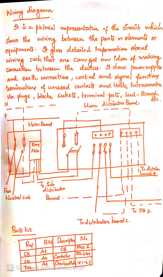
Draw a schematic or diagram of an advanced home wiring system model and identify chief components of and their locations in the system.
Homework Answers


Add Answer to:
Draw a schematic or diagram of an advanced home wiring system
model and identify chief components...
Draw a block diagram/schematic of the entire accumulator- based processor system with the clock d...
 Draw a block diagram/schematic of the entire accumulator- based processor system with the clock divider showing the connections between all four components (the 4-bit register, the 4-bit ALU, the seven-segment display, and the clock divider). You will implement this entire system on the FPGA board in lab task 5. Make this block diagram/ schematic large enough to add these additional details: i. Give each component a unique and meaningful name . İİ.Label each component's input/output ports with the appropriate names...
What are the chief components of Costco’s business model? What are the chief elements of Costco’s...
What are the chief components of Costco’s business model? What are the chief elements of Costco’s strategy? Draw a representative five-forces diagram for the North American wholesale club industry. What is your assessment of the strength of competitive pressures stemming from rivalry among Costco, Sam’s Club, and BJ’s Wholesale?
please draw a schematic of computer parts wiring, how each of the parts connected with what...
please draw a schematic of computer parts wiring, how each of the parts connected with what wires, basically showing how the wiring done in pc desktop.
The following figure shows a schematic diagram of a measuring device. (a) Identify the various components...
 The following figure shows a schematic diagram of a measuring device. (a) Identify the various components in this device b) Describe the operation of the device, explaining the function of each component and identi- 5.56 fying the nature of the measurand and the output of the device. (c) List the advantages and disadvantages of the device (d) Describe a possible application of this device. LJ 0
Question No.(6) The schematic diagram of Figure (6) represents a control system whose purpose is to...
 Question No.(6) The schematic diagram of Figure (6) represents a control system whose purpose is to hold the level of the liquid in the tank at a desired level. The liquid level is controlled by a float whose position h(t) is monitored. Draw the functional block diagram for the overall system Reservoir GEAR TRAIN --X AMPLIFIER CONTROLLER G00 Ninlet valves Nqo Float Tank Figure (6) Schematic diagram of liquid level control system
Question No.(6) The schematic diagram of Figure (6)...
Question No.(6) The schematic diagram of Figure (6) represents a control system whose purpose is to hold the level of the liquid in the tank at a desired level. The liquid level is controlled by a float whose position h(t) is monitored. Draw the functional block diagram for the overall system Reservoir GEAR TRAIN --X AMPLIFIER CONTROLLER G00 Ninlet valves Nqo Float Tank Figure (6) Schematic diagram of liquid level control system
Question No.(6) The schematic diagram of Figure (6)...
Drag the labels onto the diagram to identify the components of the somatic nervous system. Part...
 Drag the labels onto the diagram to identify the components of
the somatic nervous system.
Part A Drag the labels onto the diagram to identify the components of the somatic nervous system. Reset Help Brain Somatic motor nuclei of brain stem Somatic motor nuclei of spinal cord Spinal cord Skeletal muscle Upper motor neurons in primary motor cortex Lower motor neurons Submit Request Answer
Drag the labels onto the diagram to identify the components of
the somatic nervous system.
Part A Drag the labels onto the diagram to identify the components of the somatic nervous system. Reset Help Brain Somatic motor nuclei of brain stem Somatic motor nuclei of spinal cord Spinal cord Skeletal muscle Upper motor neurons in primary motor cortex Lower motor neurons Submit Request Answer
Question No.(5) The schematic diagram of Figure (5) represents a liquid level control system. The liquid...
 Question No.(5) The schematic diagram of Figure (5) represents a liquid level control system. The liquid level is monitored by a float whose position is h(t). Draw the functional block diagram for the overall system, showing the functional relationship between the transfer function. Reservoir GEAR TRAIN + N inlet valves + AMPLIFIER M Ch CONTROLLER ea ei Ka GA Nqn Float At) Tank Figure (5) Schematic diagram of liquid level control system
Question No.(5) The schematic diagram of Figure (5)...
Question No.(5) The schematic diagram of Figure (5) represents a liquid level control system. The liquid level is monitored by a float whose position is h(t). Draw the functional block diagram for the overall system, showing the functional relationship between the transfer function. Reservoir GEAR TRAIN + N inlet valves + AMPLIFIER M Ch CONTROLLER ea ei Ka GA Nqn Float At) Tank Figure (5) Schematic diagram of liquid level control system
Question No.(5) The schematic diagram of Figure (5)...
Draw the following schematic circuit diagram and label them accordingly: (a) Draw the schematic for a...
Draw the following schematic circuit diagram and label them accordingly: (a) Draw the schematic for a circuit in which a 10 V battery, a 100 resistor, and a 220 resistor are all in series with one another. Determine the voltage across each resistor and the current owing through each resistor. (b) Draw the schematic for a circuit in which a 10 V battery, a 100 resistor, and a 220 resistor are all in parallel with one another. Determine the voltage...
Drag the labels onto the diagram to identify the components of the autonomic nervous system. Prag...
 Drag the labels onto the diagram to identify the components of the
autonomic nervous system.
Prag the labels onto the diagram to identify the components of the autonomic nervous system! Reset Help Cardiac muscle Smooth muscle Brain Ganglionic neurons Preganglionic neuron Visceral Effectors Adipocytes Autonomic nuclei in spinal cord Autonomic nuclei in brain stem Spinal cord Autonomic ganglia Visceral motor nuclei in hypothalamus Glands Preganglionic neuron Submit Request Answer
Drag the labels onto the diagram to identify the components of the
autonomic nervous system.
Prag the labels onto the diagram to identify the components of the autonomic nervous system! Reset Help Cardiac muscle Smooth muscle Brain Ganglionic neurons Preganglionic neuron Visceral Effectors Adipocytes Autonomic nuclei in spinal cord Autonomic nuclei in brain stem Spinal cord Autonomic ganglia Visceral motor nuclei in hypothalamus Glands Preganglionic neuron Submit Request Answer
Draw the resulting circuit diagram and include the drawing. Do not simply redraw the schematic that was provided- draw the components and where to place them on the breadboard. Consider the circuit s...
 Draw the resulting circuit diagram and include the drawing. Do
not simply redraw the schematic that was provided- draw the
components and where to place them on the breadboard.
Consider the circuit shown in Figure 2.2, which adds an LED at the output of your light-sensitive voltage divider 2.2 kΩ 100 Ω Photocell Figure 2.2-Circuit diagram for a photocell-based variable voltage divider.
Consider the circuit shown in Figure 2.2, which adds an LED at the output of your light-sensitive voltage...
Draw the resulting circuit diagram and include the drawing. Do
not simply redraw the schematic that was provided- draw the
components and where to place them on the breadboard.
Consider the circuit shown in Figure 2.2, which adds an LED at the output of your light-sensitive voltage divider 2.2 kΩ 100 Ω Photocell Figure 2.2-Circuit diagram for a photocell-based variable voltage divider.
Consider the circuit shown in Figure 2.2, which adds an LED at the output of your light-sensitive voltage...
 Draw a block diagram/schematic of the entire accumulator- based processor system with the clock divider showing the connections between all four components (the 4-bit register, the 4-bit ALU, the seven-segment display, and the clock divider). You will implement this entire system on the FPGA board in lab task 5. Make this block diagram/ schematic large enough to add these additional details: i. Give each component a unique and meaningful name . İİ.Label each component's input/output ports with the appropriate names...
 The following figure shows a schematic diagram of a measuring device. (a) Identify the various components in this device b) Describe the operation of the device, explaining the function of each component and identi- 5.56 fying the nature of the measurand and the output of the device. (c) List the advantages and disadvantages of the device (d) Describe a possible application of this device. LJ 0
 Question No.(6) The schematic diagram of Figure (6) represents a control system whose purpose is to hold the level of the liquid in the tank at a desired level. The liquid level is controlled by a float whose position h(t) is monitored. Draw the functional block diagram for the overall system Reservoir GEAR TRAIN --X AMPLIFIER CONTROLLER G00 Ninlet valves Nqo Float Tank Figure (6) Schematic diagram of liquid level control system
Question No.(6) The schematic diagram of Figure (6)...
Question No.(6) The schematic diagram of Figure (6) represents a control system whose purpose is to hold the level of the liquid in the tank at a desired level. The liquid level is controlled by a float whose position h(t) is monitored. Draw the functional block diagram for the overall system Reservoir GEAR TRAIN --X AMPLIFIER CONTROLLER G00 Ninlet valves Nqo Float Tank Figure (6) Schematic diagram of liquid level control system
Question No.(6) The schematic diagram of Figure (6)...
 Drag the labels onto the diagram to identify the components of
the somatic nervous system.
Part A Drag the labels onto the diagram to identify the components of the somatic nervous system. Reset Help Brain Somatic motor nuclei of brain stem Somatic motor nuclei of spinal cord Spinal cord Skeletal muscle Upper motor neurons in primary motor cortex Lower motor neurons Submit Request Answer
Drag the labels onto the diagram to identify the components of
the somatic nervous system.
Part A Drag the labels onto the diagram to identify the components of the somatic nervous system. Reset Help Brain Somatic motor nuclei of brain stem Somatic motor nuclei of spinal cord Spinal cord Skeletal muscle Upper motor neurons in primary motor cortex Lower motor neurons Submit Request Answer
 Question No.(5) The schematic diagram of Figure (5) represents a liquid level control system. The liquid level is monitored by a float whose position is h(t). Draw the functional block diagram for the overall system, showing the functional relationship between the transfer function. Reservoir GEAR TRAIN + N inlet valves + AMPLIFIER M Ch CONTROLLER ea ei Ka GA Nqn Float At) Tank Figure (5) Schematic diagram of liquid level control system
Question No.(5) The schematic diagram of Figure (5)...
Question No.(5) The schematic diagram of Figure (5) represents a liquid level control system. The liquid level is monitored by a float whose position is h(t). Draw the functional block diagram for the overall system, showing the functional relationship between the transfer function. Reservoir GEAR TRAIN + N inlet valves + AMPLIFIER M Ch CONTROLLER ea ei Ka GA Nqn Float At) Tank Figure (5) Schematic diagram of liquid level control system
Question No.(5) The schematic diagram of Figure (5)...
 Drag the labels onto the diagram to identify the components of the
autonomic nervous system.
Prag the labels onto the diagram to identify the components of the autonomic nervous system! Reset Help Cardiac muscle Smooth muscle Brain Ganglionic neurons Preganglionic neuron Visceral Effectors Adipocytes Autonomic nuclei in spinal cord Autonomic nuclei in brain stem Spinal cord Autonomic ganglia Visceral motor nuclei in hypothalamus Glands Preganglionic neuron Submit Request Answer
Drag the labels onto the diagram to identify the components of the
autonomic nervous system.
Prag the labels onto the diagram to identify the components of the autonomic nervous system! Reset Help Cardiac muscle Smooth muscle Brain Ganglionic neurons Preganglionic neuron Visceral Effectors Adipocytes Autonomic nuclei in spinal cord Autonomic nuclei in brain stem Spinal cord Autonomic ganglia Visceral motor nuclei in hypothalamus Glands Preganglionic neuron Submit Request Answer
 Draw the resulting circuit diagram and include the drawing. Do
not simply redraw the schematic that was provided- draw the
components and where to place them on the breadboard.
Consider the circuit shown in Figure 2.2, which adds an LED at the output of your light-sensitive voltage divider 2.2 kΩ 100 Ω Photocell Figure 2.2-Circuit diagram for a photocell-based variable voltage divider.
Consider the circuit shown in Figure 2.2, which adds an LED at the output of your light-sensitive voltage...
Draw the resulting circuit diagram and include the drawing. Do
not simply redraw the schematic that was provided- draw the
components and where to place them on the breadboard.
Consider the circuit shown in Figure 2.2, which adds an LED at the output of your light-sensitive voltage divider 2.2 kΩ 100 Ω Photocell Figure 2.2-Circuit diagram for a photocell-based variable voltage divider.
Consider the circuit shown in Figure 2.2, which adds an LED at the output of your light-sensitive voltage...
Most questions answered within 3 hours.
-
26) Briefly describe, using words or simple diagrams, the
chemiosmotic theory for coupling oxidation to phosphorylation...
asked 1 hour ago -
Suppose that XX is a random variable with mean 16 and standard
deviation 5 . Also...
asked 2 hours ago -
Calculate the number density of argon gas at a temperature of
24C and a pressure of...
asked 5 hours ago -
Alternative
Classification
How to Estimate
Probabilities from Data? ( For continuous Attributes)
And How to generate...
asked 5 hours ago -
An explosion breaks a 20.0-kg object into three parts. The
object is initially moving at a...
asked 6 hours ago -
Calculate the approximate number of residues of Rubisco, which
is involved in carbon fixation in plants,...
asked 7 hours ago -
Other decisions about scientific claims can have a much broader
impact.ENERGYarrow-10x10.png, environment, health, security - all...
asked 8 hours ago -
I need to write a research paper and work cited about this
topic: The United States...
asked 8 hours ago -
Hello! I was wondering if I could have some help?
If the vapor pressure of carvone...
asked 9 hours ago -
An economist wants to estimate the mean per capita income (in
thousands of dollars) for a...
asked 9 hours ago -
What would be the input/output characteristic of a circuit
obtained by putting two of your 2's-complementers...
asked 9 hours ago -
In Drosophila, the transition from the syncytial blastoderm
stage to the cellular blastoderm stage is a...
asked 9 hours ago