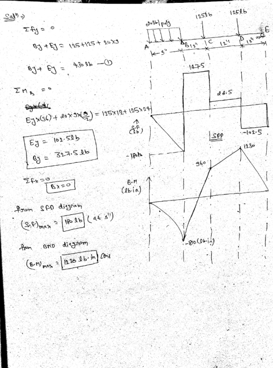
For the beam with the illustrated load, construct the shear and moment diagrams, and identify the shear and maximum moment.

Homework Answers
Add Answer to:
For the beam with the illustrated load, construct the shear and
moment diagrams, and identify the...
I need the reactions on the supports D and C plus the shear and moment diagrams...
 I need the reactions on the supports D and C plus the
shear and moment diagrams for sections AB and CD
blema 3. structura que se muestra en la figura tiene una sección transversal uniforme y carga distribuida de 1.5 kN/m. a. Dibuje el diagrama de cuerpo libre. b. Determine las reacciones en los soportes. Determine y dibuje el diagrama de fuerza cortante y de momento interno en el segmento AB. Determine y dibuje el diagrama de fuerza cortante y...
I need the reactions on the supports D and C plus the
shear and moment diagrams for sections AB and CD
blema 3. structura que se muestra en la figura tiene una sección transversal uniforme y carga distribuida de 1.5 kN/m. a. Dibuje el diagrama de cuerpo libre. b. Determine las reacciones en los soportes. Determine y dibuje el diagrama de fuerza cortante y de momento interno en el segmento AB. Determine y dibuje el diagrama de fuerza cortante y...
The symmetrical beam of the figure is subjected to a triangular load in the central section...
 The symmetrical beam of the figure is subjected to a triangular load in the central section BC and loads point on cantilevers A and D. It is requested to calculate the reactions in the supports and the shear and the moment flector at center point E.Problema 2: La viga simétrica de la figura está sometida a una carga triangular en el tramo central BC y a cargas puntuales en los voladizos A y D. Se pide calcular las reacciones en...
q= 5 p= 20 The simple concrete beam shown in the figure has a cross section...
 q= 5
p= 20
The simple concrete beam shown in the figure has a
cross section of 450x700 mm2 and knowing that the maximum
capacities of the concrete are those shown in the attached table
determine: A. The reactions in supports A and D. (table 1 and 2) B.
The bending moment equation. C. The corresponding values in table
3 D. The shear force equation. E. The corresponding values in
Table 4 F. The shear force diagram. (Draw the values...
q= 5
p= 20
The simple concrete beam shown in the figure has a
cross section of 450x700 mm2 and knowing that the maximum
capacities of the concrete are those shown in the attached table
determine: A. The reactions in supports A and D. (table 1 and 2) B.
The bending moment equation. C. The corresponding values in table
3 D. The shear force equation. E. The corresponding values in
Table 4 F. The shear force diagram. (Draw the values...
Consider the beam with the six load conditions shown (Units in SI) Determine which of the load sy...
 Consider the beam with the six load conditions shown (Units in
SI) Determine which of the load systems are equivalent. Password:
use the source as a reference. For two systems to be equivalent
they have to have the same Moments and resultant forces.
II Considere la viga con las seis condiciones de carga mostradas (Unidades en SI). Determine cuáles de los sistemas de carga son equivalentes. Clave: use el origen como referencia. Para que dos sistemas sean equivalentes tienen que...
Consider the beam with the six load conditions shown (Units in
SI) Determine which of the load systems are equivalent. Password:
use the source as a reference. For two systems to be equivalent
they have to have the same Moments and resultant forces.
II Considere la viga con las seis condiciones de carga mostradas (Unidades en SI). Determine cuáles de los sistemas de carga son equivalentes. Clave: use el origen como referencia. Para que dos sistemas sean equivalentes tienen que...
4. SHEAR AND MOMENT DIAGRAMS Determine the shear and moment diagrams for the beam shown below....
 4. SHEAR AND MOMENT DIAGRAMS Determine the shear and moment diagrams for the beam shown below. There is a pin at A and a rocker at B. a. There are 3 sections. Draw the FBD for each section. Also, give the shear and moment equation for each section. 125 lb/ft 1000 lb х 10 ft 6 ft 10 ft
4. SHEAR AND MOMENT DIAGRAMS Determine the shear and moment diagrams for the beam shown below....
 4. SHEAR AND MOMENT DIAGRAMS Determine the shear and moment diagrams for the beam shown below. There is a pin at A and a rocker at B. a. There are 3 sections. Draw the FBD for each section. Also, give the shear and moment equation for each section. у 125 lb/ft 1000 lb х A 10 ft B 6 ft 10 ft
4. SHEAR AND MOMENT DIAGRAMS Determine the shear and moment diagrams for the beam shown below....
 4. SHEAR AND MOMENT DIAGRAMS Determine the shear and moment diagrams for the beam shown below. There is a pin at A and a rocker at B. a. There are 3 sections. Draw the FBD for each section. Also, give the shear and moment equation for each section. у 125 lb/ft 1000 lb Х A B 10 ft 6 ft 10 ft
4. SHEAR AND MOMENT DIAGRAMS Determine the shear and moment diagrams for the beam shown below....
 4. SHEAR AND MOMENT DIAGRAMS Determine the shear and moment diagrams for the beam shown below. There is a pin at A and a rocker at B. a. There are 3 sections. Draw the FBD for each section. Also, give the shear and moment equation for each section. у 125 lb/ft 1000 lb 10 ft 6 ft 10 ft B
There is a simply supported vean of W12x26 steel according to AISC 360-16. which has a...
 There is a simply supported vean of W12x26 steel according to
AISC 360-16. which has a light of 1.50 m and that supports a
concentrated load in the center of the light of 15KN. For this
beam
1: calculate shear deformations using the castiglian
method
2: calculate flexion deformations using the castiglian method
Instrucciones Se tiene una viga simplemente apoyada de acero W12x26 según el AISC 360-16, que tiene una luz de 1.50 m y que soporta una carga concentrada...
There is a simply supported vean of W12x26 steel according to
AISC 360-16. which has a light of 1.50 m and that supports a
concentrated load in the center of the light of 15KN. For this
beam
1: calculate shear deformations using the castiglian
method
2: calculate flexion deformations using the castiglian method
Instrucciones Se tiene una viga simplemente apoyada de acero W12x26 según el AISC 360-16, que tiene una luz de 1.50 m y que soporta una carga concentrada...
Use the dislpacement method of analysis: A)Calculate the bending moments in each member b) Calculate the...
 Use the dislpacement method of analysis:
A)Calculate the bending moments in each member
b) Calculate the shear for each member
c)Draw the shear and bending diagrams
Problema 1. Use el método de Pendiente-Desviación para determinar los momentos y cortantes en extremo de barra para los segmentos AB y BC para la viga mostrada. Considere El=constante. Unidades [ kN, m] a) Calcule los momentos en extremo de barra para todos los elementos; b) Obtenga los cortantes para todos los elementos; c)...
Use the dislpacement method of analysis:
A)Calculate the bending moments in each member
b) Calculate the shear for each member
c)Draw the shear and bending diagrams
Problema 1. Use el método de Pendiente-Desviación para determinar los momentos y cortantes en extremo de barra para los segmentos AB y BC para la viga mostrada. Considere El=constante. Unidades [ kN, m] a) Calcule los momentos en extremo de barra para todos los elementos; b) Obtenga los cortantes para todos los elementos; c)...
 I need the reactions on the supports D and C plus the
shear and moment diagrams for sections AB and CD
blema 3. structura que se muestra en la figura tiene una sección transversal uniforme y carga distribuida de 1.5 kN/m. a. Dibuje el diagrama de cuerpo libre. b. Determine las reacciones en los soportes. Determine y dibuje el diagrama de fuerza cortante y de momento interno en el segmento AB. Determine y dibuje el diagrama de fuerza cortante y...
I need the reactions on the supports D and C plus the
shear and moment diagrams for sections AB and CD
blema 3. structura que se muestra en la figura tiene una sección transversal uniforme y carga distribuida de 1.5 kN/m. a. Dibuje el diagrama de cuerpo libre. b. Determine las reacciones en los soportes. Determine y dibuje el diagrama de fuerza cortante y de momento interno en el segmento AB. Determine y dibuje el diagrama de fuerza cortante y...
 The symmetrical beam of the figure is subjected to a triangular load in the central section BC and loads point on cantilevers A and D. It is requested to calculate the reactions in the supports and the shear and the moment flector at center point E.Problema 2: La viga simétrica de la figura está sometida a una carga triangular en el tramo central BC y a cargas puntuales en los voladizos A y D. Se pide calcular las reacciones en...
 q= 5
p= 20
The simple concrete beam shown in the figure has a
cross section of 450x700 mm2 and knowing that the maximum
capacities of the concrete are those shown in the attached table
determine: A. The reactions in supports A and D. (table 1 and 2) B.
The bending moment equation. C. The corresponding values in table
3 D. The shear force equation. E. The corresponding values in
Table 4 F. The shear force diagram. (Draw the values...
q= 5
p= 20
The simple concrete beam shown in the figure has a
cross section of 450x700 mm2 and knowing that the maximum
capacities of the concrete are those shown in the attached table
determine: A. The reactions in supports A and D. (table 1 and 2) B.
The bending moment equation. C. The corresponding values in table
3 D. The shear force equation. E. The corresponding values in
Table 4 F. The shear force diagram. (Draw the values...
 Consider the beam with the six load conditions shown (Units in
SI) Determine which of the load systems are equivalent. Password:
use the source as a reference. For two systems to be equivalent
they have to have the same Moments and resultant forces.
II Considere la viga con las seis condiciones de carga mostradas (Unidades en SI). Determine cuáles de los sistemas de carga son equivalentes. Clave: use el origen como referencia. Para que dos sistemas sean equivalentes tienen que...
Consider the beam with the six load conditions shown (Units in
SI) Determine which of the load systems are equivalent. Password:
use the source as a reference. For two systems to be equivalent
they have to have the same Moments and resultant forces.
II Considere la viga con las seis condiciones de carga mostradas (Unidades en SI). Determine cuáles de los sistemas de carga son equivalentes. Clave: use el origen como referencia. Para que dos sistemas sean equivalentes tienen que...
 4. SHEAR AND MOMENT DIAGRAMS Determine the shear and moment diagrams for the beam shown below. There is a pin at A and a rocker at B. a. There are 3 sections. Draw the FBD for each section. Also, give the shear and moment equation for each section. 125 lb/ft 1000 lb х 10 ft 6 ft 10 ft
 4. SHEAR AND MOMENT DIAGRAMS Determine the shear and moment diagrams for the beam shown below. There is a pin at A and a rocker at B. a. There are 3 sections. Draw the FBD for each section. Also, give the shear and moment equation for each section. у 125 lb/ft 1000 lb х A 10 ft B 6 ft 10 ft
 4. SHEAR AND MOMENT DIAGRAMS Determine the shear and moment diagrams for the beam shown below. There is a pin at A and a rocker at B. a. There are 3 sections. Draw the FBD for each section. Also, give the shear and moment equation for each section. у 125 lb/ft 1000 lb Х A B 10 ft 6 ft 10 ft
 4. SHEAR AND MOMENT DIAGRAMS Determine the shear and moment diagrams for the beam shown below. There is a pin at A and a rocker at B. a. There are 3 sections. Draw the FBD for each section. Also, give the shear and moment equation for each section. у 125 lb/ft 1000 lb 10 ft 6 ft 10 ft B
 There is a simply supported vean of W12x26 steel according to
AISC 360-16. which has a light of 1.50 m and that supports a
concentrated load in the center of the light of 15KN. For this
beam
1: calculate shear deformations using the castiglian
method
2: calculate flexion deformations using the castiglian method
Instrucciones Se tiene una viga simplemente apoyada de acero W12x26 según el AISC 360-16, que tiene una luz de 1.50 m y que soporta una carga concentrada...
There is a simply supported vean of W12x26 steel according to
AISC 360-16. which has a light of 1.50 m and that supports a
concentrated load in the center of the light of 15KN. For this
beam
1: calculate shear deformations using the castiglian
method
2: calculate flexion deformations using the castiglian method
Instrucciones Se tiene una viga simplemente apoyada de acero W12x26 según el AISC 360-16, que tiene una luz de 1.50 m y que soporta una carga concentrada...
 Use the dislpacement method of analysis:
A)Calculate the bending moments in each member
b) Calculate the shear for each member
c)Draw the shear and bending diagrams
Problema 1. Use el método de Pendiente-Desviación para determinar los momentos y cortantes en extremo de barra para los segmentos AB y BC para la viga mostrada. Considere El=constante. Unidades [ kN, m] a) Calcule los momentos en extremo de barra para todos los elementos; b) Obtenga los cortantes para todos los elementos; c)...
Use the dislpacement method of analysis:
A)Calculate the bending moments in each member
b) Calculate the shear for each member
c)Draw the shear and bending diagrams
Problema 1. Use el método de Pendiente-Desviación para determinar los momentos y cortantes en extremo de barra para los segmentos AB y BC para la viga mostrada. Considere El=constante. Unidades [ kN, m] a) Calcule los momentos en extremo de barra para todos los elementos; b) Obtenga los cortantes para todos los elementos; c)...
Most questions answered within 3 hours.
-
________40. Which of the following is the correct sequence of
steps in the general
adaptation...
asked 7 minutes ago -
Hi, Please draw the network diagram.
Activity D on a CPM network has predecessors B and...
asked 9 minutes ago -
Explain how bacteria can be used in Food production
Explain the fermentation of Milk & Cheese...
asked 14 minutes ago -
A uniform, solid sphere of radius 4.50 cm and mass 4.50 kg
starts with a purely...
asked 29 minutes ago -
Consider the prisoners’ dilemma we discussed in class, with the
following twist. If both prisoners choose...
asked 13 minutes ago -
The length of a pencil is measured to be 10.00 cm with a ruler.
What is...
asked 25 minutes ago -
A 120 cm^3 box contains helium at a pressure of 1.80 atm and a
temperature of...
asked 30 minutes ago -
Given that Kb for the weak base analine is 3.8 X
10-10, which of the following...
asked 32 minutes ago -
A sniper fires a rifle bullet into a gasoline tank, making a
hole 51.0 m below...
asked 33 minutes ago -
The US Census Bureau gathered data regarding yearly gas sales
for residents of different states. Wyoming...
asked 53 minutes ago -
A person in a casino decides to play blackjack until he loses a
game, but he...
asked 56 minutes ago -
mode field diameter (MFD) is an important parameter in
characterizing single mode fibre properties which takes...
asked 47 minutes ago