
Homework Answers


Add Answer to:
Q3: The structural element in the figure carries the following loads. P= 5 kN, V =...
Problem 2: A circular shaft transmits power as shown with pulley loads. The shaft carries a...
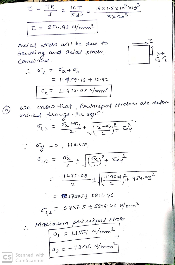
 Problem 2: A circular shaft transmits power as shown with pulley loads. The shaft carries a torque, bending, shear and axial loads. Draw LVM diagram to find Mmax and Vmax. Show all loads (moments and forces) on the circular x-section of the shaft below. Use double arrows for moments. Compute shear and normal stresses and show them on the same section. Create stress elements for points A and B of the section. Combine the stresses and compute Cuau (Tresca) and...
A circular shaft transmits power as shown with pulley loads. The shaft carries a torque, bending,...
 A circular shaft transmits power as shown with pulley loads. The shaft carries a torque, bending, shear and axial loads. Draw LVM diagram to find Mmax and Vmax. Show all loads (moments and forces) on the circular x-section of the shaft below. Use double arrows for moments. Compute shear and normal stresses and show them on the same section. Create stress elements for points A and B of the section. Combine the stresses and compute tmax (Tresca) and om (von...
Problem 2: A circular shaft transmits power as shown with pulley loads. The shaft carries a...
 Problem 2: A circular shaft transmits power as shown with pulley loads. The shaft carries a torque, bending, shear and axial loads. Draw LVM diagram to find Mmax and Vmax. Show all loads (moments and forces) on the circular x-section of the shaft below. Use double arrows for moments. Compute shear and normal stresses and show them on the same section. Create stress elements for points A and B of the section. Combine the stresses and compute Tmax (Tresca) and...
(a) If the wide-flange beam shown in Figure Q4a is subjected to a shear of V = 23 kN
 (a) If the wide-flange beam shown in Figure Q4a is subjected to a shear of V = 23 kN i. Calculate the moment of inertia of the cross section about the neutral axis.ii. Determine the shear stress on the web at A.(b) The state of stress at a point is shown on the element in Figure Q4b. Determine graphically using Mohr's circle i. The principal stresses. ii. The orientation of the principal planes.iii. The maximum in-plane shear stress and average normal stress at...
Q3. (30 points) For the state of plane stress shown, Stresses, σ. σ2 (b) the orientation of the p...
 please help me solve this whole mechanical design
problem
thanks
Q3. (30 points) For the state of plane stress shown, Stresses, σ. σ2 (b) the orientation of the principal stresses, s, (c) the maximum in plane shearing stress, Tmar and (d) its orientation, p. (e) the normal stress at the plane of maximum shear stress, (1) sketch of the rotated plane element for the principal stresses and the rotated plane element for maximum shear stress similar to figure 1, below...
please help me solve this whole mechanical design
problem
thanks
Q3. (30 points) For the state of plane stress shown, Stresses, σ. σ2 (b) the orientation of the principal stresses, s, (c) the maximum in plane shearing stress, Tmar and (d) its orientation, p. (e) the normal stress at the plane of maximum shear stress, (1) sketch of the rotated plane element for the principal stresses and the rotated plane element for maximum shear stress similar to figure 1, below...
The rectangular plate shown in the figure below has the given loads uniformly distributed over the...
 The rectangular plate shown in the figure below has the given loads uniformly distributed over the edges. The plate is 50 mm thick, AB is 500 mm and BC is 400 mm (a) (b) (c) (d) (e) Determine the shear forces which must operate on the edges BC and DA to maintain the equilibrium of the plate Relative to the x,y reference axes, determine the state of stress at any point P in the interior of the plate For the...
PROBLEM 2: 40% A 6 kN force is exerted on the frame which has the T cross sectio analyze the states of stress at a section taken at 800 mm from the point of n shown below. It is required to 1. Fo...
 PROBLEM 2: 40% A 6 kN force is exerted on the frame which has the T cross sectio analyze the states of stress at a section taken at 800 mm from the point of n shown below. It is required to 1. For the given T cross section, find the centroid and the area moment of inertia I,. 2. Draw the free body diagram of the free end of the frame and determine the interna loadings at the centroid of...
SX= 204MPa SY= -12MPa 2. Figure 2 shows a tubular joint subjected to moment M and...
 SX= 204MPa
SY= -12MPa
2. Figure 2 shows a tubular joint subjected to moment M and P. Due to these CLO4 loads, an element of the joint in xy plane ABCD has stress system shown in Figure 3. The values of the stresses are Oxx = SX , Oyy = SY, and Txy = 45 MPa. The values and units of measure for the stresses are as given in the data sheet. Construct Mohr's circle for the stress systems to...
SX= 204MPa
SY= -12MPa
2. Figure 2 shows a tubular joint subjected to moment M and P. Due to these CLO4 loads, an element of the joint in xy plane ABCD has stress system shown in Figure 3. The values of the stresses are Oxx = SX , Oyy = SY, and Txy = 45 MPa. The values and units of measure for the stresses are as given in the data sheet. Construct Mohr's circle for the stress systems to...
THO4 (10 pts) Take Home Date Due: 9:30am Wednesday, October 23, 2019 Name: Consider a cylindrical...
 THO4 (10 pts) Take Home Date Due: 9:30am Wednesday, October 23, 2019 Name: Consider a cylindrical pressure vessel with spherical end caps made of ASTM A516 Grade 70 steel with yield stress a,eld Tated at 335 MPa that has diameter D-3.0m, thickness t-25mm and length L-24.0m for the cylindrical portion of the pressure vessel. The cylindrical pressure vessel is pressurized internally at pressure p-2.5 MPa. Assume externally pressure to be zero. The material has modulus E-200 GPa and Poisson's ratio...
The cantilever beam of length 3L is subject to concentrated loads P and 2P and has...
 The cantilever beam of length 3L is subject to concentrated loads P and 2P and has the thin-walled cross-section illustrated below. The cross-section has uniform thickness t and moment of inertia with respect to the centroidal z-axis given by I = 3140 t4. Use t = 5 mm, L = 135 mm and P= 6 kN. 2P H 10 t 5t A P 10 t 22 L 10 t 1) Determine the numerical value of the shear force and bending...
 Problem 2: A circular shaft transmits power as shown with pulley loads. The shaft carries a torque, bending, shear and axial loads. Draw LVM diagram to find Mmax and Vmax. Show all loads (moments and forces) on the circular x-section of the shaft below. Use double arrows for moments. Compute shear and normal stresses and show them on the same section. Create stress elements for points A and B of the section. Combine the stresses and compute Cuau (Tresca) and...
 A circular shaft transmits power as shown with pulley loads. The shaft carries a torque, bending, shear and axial loads. Draw LVM diagram to find Mmax and Vmax. Show all loads (moments and forces) on the circular x-section of the shaft below. Use double arrows for moments. Compute shear and normal stresses and show them on the same section. Create stress elements for points A and B of the section. Combine the stresses and compute tmax (Tresca) and om (von...
 Problem 2: A circular shaft transmits power as shown with pulley loads. The shaft carries a torque, bending, shear and axial loads. Draw LVM diagram to find Mmax and Vmax. Show all loads (moments and forces) on the circular x-section of the shaft below. Use double arrows for moments. Compute shear and normal stresses and show them on the same section. Create stress elements for points A and B of the section. Combine the stresses and compute Tmax (Tresca) and...
 please help me solve this whole mechanical design
problem
thanks
Q3. (30 points) For the state of plane stress shown, Stresses, σ. σ2 (b) the orientation of the principal stresses, s, (c) the maximum in plane shearing stress, Tmar and (d) its orientation, p. (e) the normal stress at the plane of maximum shear stress, (1) sketch of the rotated plane element for the principal stresses and the rotated plane element for maximum shear stress similar to figure 1, below...
please help me solve this whole mechanical design
problem
thanks
Q3. (30 points) For the state of plane stress shown, Stresses, σ. σ2 (b) the orientation of the principal stresses, s, (c) the maximum in plane shearing stress, Tmar and (d) its orientation, p. (e) the normal stress at the plane of maximum shear stress, (1) sketch of the rotated plane element for the principal stresses and the rotated plane element for maximum shear stress similar to figure 1, below...
 The rectangular plate shown in the figure below has the given loads uniformly distributed over the edges. The plate is 50 mm thick, AB is 500 mm and BC is 400 mm (a) (b) (c) (d) (e) Determine the shear forces which must operate on the edges BC and DA to maintain the equilibrium of the plate Relative to the x,y reference axes, determine the state of stress at any point P in the interior of the plate For the...
 PROBLEM 2: 40% A 6 kN force is exerted on the frame which has the T cross sectio analyze the states of stress at a section taken at 800 mm from the point of n shown below. It is required to 1. For the given T cross section, find the centroid and the area moment of inertia I,. 2. Draw the free body diagram of the free end of the frame and determine the interna loadings at the centroid of...
 SX= 204MPa
SY= -12MPa
2. Figure 2 shows a tubular joint subjected to moment M and P. Due to these CLO4 loads, an element of the joint in xy plane ABCD has stress system shown in Figure 3. The values of the stresses are Oxx = SX , Oyy = SY, and Txy = 45 MPa. The values and units of measure for the stresses are as given in the data sheet. Construct Mohr's circle for the stress systems to...
SX= 204MPa
SY= -12MPa
2. Figure 2 shows a tubular joint subjected to moment M and P. Due to these CLO4 loads, an element of the joint in xy plane ABCD has stress system shown in Figure 3. The values of the stresses are Oxx = SX , Oyy = SY, and Txy = 45 MPa. The values and units of measure for the stresses are as given in the data sheet. Construct Mohr's circle for the stress systems to...
 THO4 (10 pts) Take Home Date Due: 9:30am Wednesday, October 23, 2019 Name: Consider a cylindrical pressure vessel with spherical end caps made of ASTM A516 Grade 70 steel with yield stress a,eld Tated at 335 MPa that has diameter D-3.0m, thickness t-25mm and length L-24.0m for the cylindrical portion of the pressure vessel. The cylindrical pressure vessel is pressurized internally at pressure p-2.5 MPa. Assume externally pressure to be zero. The material has modulus E-200 GPa and Poisson's ratio...
 The cantilever beam of length 3L is subject to concentrated loads P and 2P and has the thin-walled cross-section illustrated below. The cross-section has uniform thickness t and moment of inertia with respect to the centroidal z-axis given by I = 3140 t4. Use t = 5 mm, L = 135 mm and P= 6 kN. 2P H 10 t 5t A P 10 t 22 L 10 t 1) Determine the numerical value of the shear force and bending...
Most questions answered within 3 hours.
-
A projectile is launched with an initial speed of 40 m/s at an
angle of 25°...
asked 3 seconds from now -
A concentration cell is built based on the reaction:
2H+ + 2e- ----> H2
The pH...
asked 5 minutes ago -
1. Using a function, display the customer who has the highest
credit limit. Display the customer...
asked 8 minutes ago -
How many unique codes are possibly formed from two characters,
where the first character can be...
asked 10 minutes ago -
A spatially uniform electric field varies in time according
to E = Eo + 3000 t,...
asked 34 minutes ago -
An electric power station that operates at 25 kV and uses a 20:1
step-up ideal transformer...
asked 27 minutes ago -
1. If 0.02% of a 0.6 M weak acid ionizes in a solution, what is
the...
asked 14 minutes ago -
The College of Business at Northeast College is accumulating
data as a first step in the...
asked 19 minutes ago -
what is the ph of the following solutions?
150 g NH4CI dissolved into 10.0 mL of...
asked 17 minutes ago -
A flint glass plate (n = 1.66) rests on the bottom of an
aquarium tank. The...
asked 28 minutes ago -
The position in an object as a function of time is given as ?
(?) =...
asked 43 minutes ago -
Consider a different car. Its initial position at time 5 s is
5m, and it moves...
asked 24 minutes ago