
Homework Answers

![200 Complexe pain of induction is Syzja (111]x200 +0 S = otj Ž (0.255)²x200 XA S = 0+ 36.503 VA Complex power of R3 is : SR3](http://img.homeworklib.com/questions/74e14730-9433-11eb-b6fe-eb6b0c50b9d6.png?x-oss-process=image/resize,w_560)

Add Answer to:
8.22 In the phasor-domain shown in Fig. P8.22, V = 120/0° V, I = 0.3/30° A,...
About Exercise 8.4.9 In the phasor-domain circuit shown below. I-2/0° A, R1 -20 Ω, R2 1...
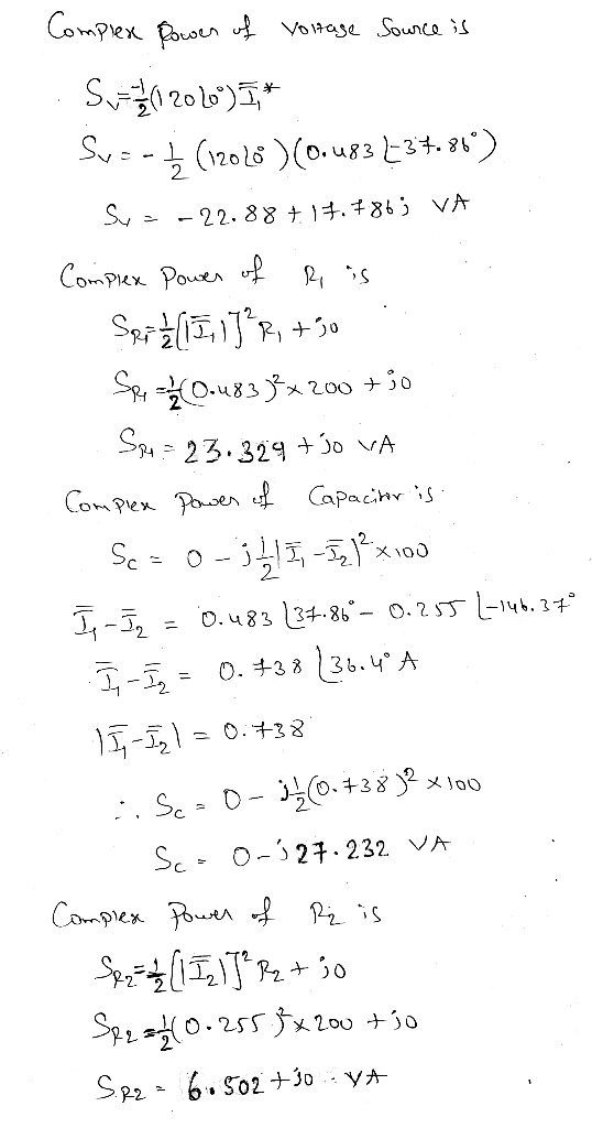
 About Exercise 8.4.9 In the phasor-domain circuit shown below. I-2/0° A, R1 -20 Ω, R2 1 Ω. R3 5 Ω.ZLI-JD Ω, ZL2-125 Ω, and R2 L a R3 Load L21 Determine S of the load.
Circuit Analysis in the s-Domain 15.3. The initial voltage across the capacitor in the circuit shown in Figure P15.3 is v(0) 1 V, and the initial current through the inductor is i(0)0 mA Find th...
 Circuit Analysis in the s-Domain 15.3. The initial voltage across the capacitor in the circuit shown in Figure P15.3 is v(0) 1 V, and the initial current through the inductor is i(0)0 mA Find the voltage vo (t) across the capacitor for t 2 0 Figure P15.3 50 mH 1 kS2 V. Volt) T 0.1 μF The circuit in the s-domain is shown below. R2 Va 1k 0.05s 1/(sC)-1e7/s Vo R1 2k V (0-ys 5/s 1/s 1 format long; 2...
1.47 It is desired to achieve a time-v the magnetic circuit of Fig. 1.41 of the form where Bo = 0...
 fig1.19 requeted
1.47 It is desired to achieve a time-v the magnetic circuit of Fig. 1.41 of the form where Bo = 0.6 T and Bi = 0.20 T. The dc field Bo is to be created by a neodymium-iron-boron magnet with magnetization characteristic of Fig. 1.19, whereas the time-varying field is to be created by a time-varying current. For Ag 7 cm2, g 0.35 cm, and N 175 turns, and based upon the neodymium-iron-boron characteristics of Fig. 1.19, find:...
fig1.19 requeted
1.47 It is desired to achieve a time-v the magnetic circuit of Fig. 1.41 of the form where Bo = 0.6 T and Bi = 0.20 T. The dc field Bo is to be created by a neodymium-iron-boron magnet with magnetization characteristic of Fig. 1.19, whereas the time-varying field is to be created by a time-varying current. For Ag 7 cm2, g 0.35 cm, and N 175 turns, and based upon the neodymium-iron-boron characteristics of Fig. 1.19, find:...
Problem No 1 (30 Marka) Apl lading test was camied out on smal Kale fondron footing, 0.3 m square, .depeh 1 mi dry sand. Theets is shown in Fig 1-1 (20 Marks 0 20 00 20 Loadina Fig. 1-I Th...
 Problem No 1 (30 Marka) Apl lading test was camied out on smal Kale fondron footing, 0.3 m square, .depeh 1 mi dry sand. Theets is shown in Fig 1-1 (20 Marks 0 20 00 20 Loadina Fig. 1-I The results of plate oading les Detenine elastic modulius(E) from plate loading est De emi e tition畩(6"om plate loading ts cohesion-o Determine the dimension of a square foing to resist load at 10000 N a the ame depth of 2 m...
 About Exercise 8.4.9 In the phasor-domain circuit shown below. I-2/0° A, R1 -20 Ω, R2 1 Ω. R3 5 Ω.ZLI-JD Ω, ZL2-125 Ω, and R2 L a R3 Load L21 Determine S of the load.
 Circuit Analysis in the s-Domain 15.3. The initial voltage across the capacitor in the circuit shown in Figure P15.3 is v(0) 1 V, and the initial current through the inductor is i(0)0 mA Find the voltage vo (t) across the capacitor for t 2 0 Figure P15.3 50 mH 1 kS2 V. Volt) T 0.1 μF The circuit in the s-domain is shown below. R2 Va 1k 0.05s 1/(sC)-1e7/s Vo R1 2k V (0-ys 5/s 1/s 1 format long; 2...
 fig1.19 requeted
1.47 It is desired to achieve a time-v the magnetic circuit of Fig. 1.41 of the form where Bo = 0.6 T and Bi = 0.20 T. The dc field Bo is to be created by a neodymium-iron-boron magnet with magnetization characteristic of Fig. 1.19, whereas the time-varying field is to be created by a time-varying current. For Ag 7 cm2, g 0.35 cm, and N 175 turns, and based upon the neodymium-iron-boron characteristics of Fig. 1.19, find:...
fig1.19 requeted
1.47 It is desired to achieve a time-v the magnetic circuit of Fig. 1.41 of the form where Bo = 0.6 T and Bi = 0.20 T. The dc field Bo is to be created by a neodymium-iron-boron magnet with magnetization characteristic of Fig. 1.19, whereas the time-varying field is to be created by a time-varying current. For Ag 7 cm2, g 0.35 cm, and N 175 turns, and based upon the neodymium-iron-boron characteristics of Fig. 1.19, find:...
 Problem No 1 (30 Marka) Apl lading test was camied out on smal Kale fondron footing, 0.3 m square, .depeh 1 mi dry sand. Theets is shown in Fig 1-1 (20 Marks 0 20 00 20 Loadina Fig. 1-I The results of plate oading les Detenine elastic modulius(E) from plate loading est De emi e tition畩(6"om plate loading ts cohesion-o Determine the dimension of a square foing to resist load at 10000 N a the ame depth of 2 m...
Most questions answered within 3 hours.
-
> Women’s pulse rates are normally distributed with a mean of
68.5 beats per minute and...
asked 4 minutes ago -
Briefly describe an aspect of the strengths perspective that is
consistent with your own understanding of...
asked 6 minutes ago -
Step by step method of using Sparse Identification of Nonlinear
Dynamics (SINDy) to model your own...
asked 13 minutes ago -
3) What are the typical social structures in a global city?
asked 3 hours ago -
Luther Corporation
Consolidated Balance Sheet
December 31, 2019 and 2018 (in $ millions)
Assets
2019
2018...
asked 3 hours ago -
(Expected rate of return and risk) Carter Inc. is evaluating a
security. Calculate the investment’s expected...
asked 6 hours ago -
What specific indicators can point to lack of progress for
African Americans in American society?
asked 7 hours ago -
1-The Electrons in a beam are moving at 2.7×10⁸ m/s in an
electric field of 15000...
asked 7 hours ago -
A gas tank is a vertical cylinder. It has a radius of 1m, a
height of...
asked 7 hours ago -
Accent Software faces the following conditions. All of these
support Accent’s use of a market-penetration pricing...
asked 8 hours ago -
A mathematically inclined friend emails you the following
instructions: "Meet me in the cafeteria the first...
asked 8 hours ago -
A monopoly sells in two countries . The demand curves in the two
countries are p1...
asked 9 hours ago