


Homework Answers


Add Answer to:
For the circuit shown in the figure (ε-3.50 V, R-5.00 Ω), calculate the following quantities. 12,0...
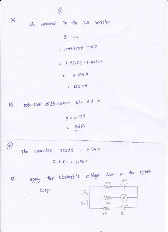
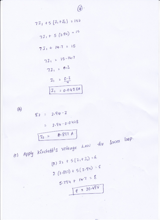
The ammeter shown in the figure below reads 2.92 A. Find 1112, and ε 2 15.0...
 The ammeter shown in the figure below reads 2.92 A. Find 1112, and ε 2 15.0 V 7.00 Ω 5.00 Ω 2.00 Ω +1- Need Help?Read It Watch It
The ammeter shown in the figure below reads 2.48 A. Find the following. (a) I1 =...
 The ammeter shown in the
figure below reads 2.48 A. Find the following. (a) I1 = Incorrect:
Your answer is incorrect. Consider applying Kirchhoff's voltage
rule to the upper loop. A (b) I2 = A (c) e m f = V
The ammeter shown in the figure below reads 2.48 A. Find the following. 15.0 V 7.00 Ω 5.00 Ω +1,- 2.00 Ω (a) 11 5.52 Consider applying Kirchhoff's voltage rule to the upper loop. A (b) I2 - (c)...
The ammeter shown in the
figure below reads 2.48 A. Find the following. (a) I1 = Incorrect:
Your answer is incorrect. Consider applying Kirchhoff's voltage
rule to the upper loop. A (b) I2 = A (c) e m f = V
The ammeter shown in the figure below reads 2.48 A. Find the following. 15.0 V 7.00 Ω 5.00 Ω +1,- 2.00 Ω (a) 11 5.52 Consider applying Kirchhoff's voltage rule to the upper loop. A (b) I2 - (c)...
For the circuit shown in the figure, calculate the following. (Assume ε = 8.40 V and R = 5.94 Ω.)
 For the circuit shown in the figure, calculate the following. (Assume ε = 8.40 V and R = 5.94 Ω.) (a) the current in the 2.00-12 resistor (Enter the magnitude.) (b) the potential difference between points a and b, ΔV = Vb - Va
The ammeter shown in the figure registers a current of 2 Ampere. Calculate the value of...
 The ammeter shown in the figure registers a current of 2 Ampere. Calculate the value of E.
A. 20.25 V
B. 12.1 V
C. 12V
D. 18.5 V
E. 24 V
F. 12.6
G. 6.5 V
H. 10.5 V7.00 Ω 15.0V και 5.00 Ω -- A 14 ε 2.00 Ω -,
The ammeter shown in the figure registers a current of 2 Ampere. Calculate the value of E.
A. 20.25 V
B. 12.1 V
C. 12V
D. 18.5 V
E. 24 V
F. 12.6
G. 6.5 V
H. 10.5 V7.00 Ω 15.0V και 5.00 Ω -- A 14 ε 2.00 Ω -,
What are the expected readings of the following in the figure below? (R-8.40 Ω, AV-670 V)...
 What are the expected readings of the following in the figure below? (R-8.40 Ω, AV-670 V) 10.0 Ω R 4.50 V (a) ideal ammeter mA (b) ideal voltmeter
What are the expected readings of the following in the figure below? (R = 8.60 Ω,...
 What are the expected readings of the following in the figure
below? (R = 8.60 Ω, ΔV = 5.90 V)
(a) ideal ammeter
(b) ideal voltmeter
What are the expected readings of the following in the figure
below? (R = 8.60 Ω, ΔV = 5.90 V)
(a) ideal ammeter
(b) ideal voltmeter
For the circuit shown in Fig. 6, calculate:(a) the current in the 2.00−Ω resistor.(b) the potential...
 For the circuit shown in Fig. 6, calculate:(a) the current in
the 2.00−Ω resistor.(b) the potential difference between points a
and b.
Assume that the components on Fig. 7 have the following
values:V1 = 10.0 V , V2 = 15.0 V , R1 = 5.0 Ω, R1 = 5.00 Ω, R2 =
10.0 Ω, R3 = 15.0 Ω, R4 = 20.0 Ω. (a) Find the current trough each
branch of the circuit. (b) Find the power dissipated in each
circuit...
For the circuit shown in Fig. 6, calculate:(a) the current in
the 2.00−Ω resistor.(b) the potential difference between points a
and b.
Assume that the components on Fig. 7 have the following
values:V1 = 10.0 V , V2 = 15.0 V , R1 = 5.0 Ω, R1 = 5.00 Ω, R2 =
10.0 Ω, R3 = 15.0 Ω, R4 = 20.0 Ω. (a) Find the current trough each
branch of the circuit. (b) Find the power dissipated in each
circuit...
The ammeter shown in the figure below reads 1.86 A. Find I1, I2, and E I1...
 The ammeter shown in the figure below reads 1.86 A. Find I1, I2, and E I1 А I2 A V 15.0 V 7.00 5.00 W + 2.00
for the circuit in the following figure, both meters are idealized.please break it down the circuit,...
 for the circuit in the following figure, both meters are
idealized.please break it down the circuit, and answer questions a
and b.
For the circuit shown in the following figure both meters are idealized, the battery has no appreciable internal resistance, and the ammeter reads 1.37 A. (Let R1-52.0 Ω, R2-27.0 Ω, and R3-R4-17 Ω·) (a) What does the voltmeter read? (b) what is the emf ε of the battery? R3 Ri R4 10.012 35.0 Ω a. 256 V b.465...
for the circuit in the following figure, both meters are
idealized.please break it down the circuit, and answer questions a
and b.
For the circuit shown in the following figure both meters are idealized, the battery has no appreciable internal resistance, and the ammeter reads 1.37 A. (Let R1-52.0 Ω, R2-27.0 Ω, and R3-R4-17 Ω·) (a) What does the voltmeter read? (b) what is the emf ε of the battery? R3 Ri R4 10.012 35.0 Ω a. 256 V b.465...
 The ammeter shown in the figure below reads 2.92 A. Find 1112, and ε 2 15.0 V 7.00 Ω 5.00 Ω 2.00 Ω +1- Need Help?Read It Watch It
 The ammeter shown in the
figure below reads 2.48 A. Find the following. (a) I1 = Incorrect:
Your answer is incorrect. Consider applying Kirchhoff's voltage
rule to the upper loop. A (b) I2 = A (c) e m f = V
The ammeter shown in the figure below reads 2.48 A. Find the following. 15.0 V 7.00 Ω 5.00 Ω +1,- 2.00 Ω (a) 11 5.52 Consider applying Kirchhoff's voltage rule to the upper loop. A (b) I2 - (c)...
The ammeter shown in the
figure below reads 2.48 A. Find the following. (a) I1 = Incorrect:
Your answer is incorrect. Consider applying Kirchhoff's voltage
rule to the upper loop. A (b) I2 = A (c) e m f = V
The ammeter shown in the figure below reads 2.48 A. Find the following. 15.0 V 7.00 Ω 5.00 Ω +1,- 2.00 Ω (a) 11 5.52 Consider applying Kirchhoff's voltage rule to the upper loop. A (b) I2 - (c)...
 The ammeter shown in the figure registers a current of 2 Ampere. Calculate the value of E.
A. 20.25 V
B. 12.1 V
C. 12V
D. 18.5 V
E. 24 V
F. 12.6
G. 6.5 V
H. 10.5 V7.00 Ω 15.0V και 5.00 Ω -- A 14 ε 2.00 Ω -,
The ammeter shown in the figure registers a current of 2 Ampere. Calculate the value of E.
A. 20.25 V
B. 12.1 V
C. 12V
D. 18.5 V
E. 24 V
F. 12.6
G. 6.5 V
H. 10.5 V7.00 Ω 15.0V και 5.00 Ω -- A 14 ε 2.00 Ω -,
 What are the expected readings of the following in the figure below? (R-8.40 Ω, AV-670 V) 10.0 Ω R 4.50 V (a) ideal ammeter mA (b) ideal voltmeter
 What are the expected readings of the following in the figure
below? (R = 8.60 Ω, ΔV = 5.90 V)
(a) ideal ammeter
(b) ideal voltmeter
What are the expected readings of the following in the figure
below? (R = 8.60 Ω, ΔV = 5.90 V)
(a) ideal ammeter
(b) ideal voltmeter
 For the circuit shown in Fig. 6, calculate:(a) the current in
the 2.00−Ω resistor.(b) the potential difference between points a
and b.
Assume that the components on Fig. 7 have the following
values:V1 = 10.0 V , V2 = 15.0 V , R1 = 5.0 Ω, R1 = 5.00 Ω, R2 =
10.0 Ω, R3 = 15.0 Ω, R4 = 20.0 Ω. (a) Find the current trough each
branch of the circuit. (b) Find the power dissipated in each
circuit...
For the circuit shown in Fig. 6, calculate:(a) the current in
the 2.00−Ω resistor.(b) the potential difference between points a
and b.
Assume that the components on Fig. 7 have the following
values:V1 = 10.0 V , V2 = 15.0 V , R1 = 5.0 Ω, R1 = 5.00 Ω, R2 =
10.0 Ω, R3 = 15.0 Ω, R4 = 20.0 Ω. (a) Find the current trough each
branch of the circuit. (b) Find the power dissipated in each
circuit...
 The ammeter shown in the figure below reads 1.86 A. Find I1, I2, and E I1 А I2 A V 15.0 V 7.00 5.00 W + 2.00
 for the circuit in the following figure, both meters are
idealized.please break it down the circuit, and answer questions a
and b.
For the circuit shown in the following figure both meters are idealized, the battery has no appreciable internal resistance, and the ammeter reads 1.37 A. (Let R1-52.0 Ω, R2-27.0 Ω, and R3-R4-17 Ω·) (a) What does the voltmeter read? (b) what is the emf ε of the battery? R3 Ri R4 10.012 35.0 Ω a. 256 V b.465...
for the circuit in the following figure, both meters are
idealized.please break it down the circuit, and answer questions a
and b.
For the circuit shown in the following figure both meters are idealized, the battery has no appreciable internal resistance, and the ammeter reads 1.37 A. (Let R1-52.0 Ω, R2-27.0 Ω, and R3-R4-17 Ω·) (a) What does the voltmeter read? (b) what is the emf ε of the battery? R3 Ri R4 10.012 35.0 Ω a. 256 V b.465...
Most questions answered within 3 hours.
-
Linear programming is an excellent technique yet is not applied
nearly enough in the “real world.”...
asked 4 minutes ago -
What three alkenes yield 3-methylpentane on catalytic
hydrogenation?
asked 4 minutes ago -
In JAVA Create a program with an array with the following
data:
50 12 31 76...
asked 7 minutes ago -
Using a hormone of the hypothalamic-anterior pituitary axis,
describe or diagram how negative feedback loops regulate...
asked 5 minutes ago -
1,1-dimethylcyclorohexane reacts with single bromine atom
asked 28 minutes ago -
The completed Lewis structure of CO2 contains a total
of 0,1,2,3,4,5,6,7,8 covalent bonds
and 0,1,2,3,4,5,6,7,8 lone pairs.
NOTE:...
asked 34 minutes ago -
A 0.0510 M solution of an organic acid has an
[H+] of 7.50×10⁻⁴M .
What is...
asked 31 minutes ago -
what is the profit-maximizing output condition that a
monopolistically competitive firm must satisfy? a) price charged...
asked 36 minutes ago -
Consider the set of ordered pairs shown below. Assuming that the
regression equation is y=3.513+0.429x and...
asked 57 minutes ago -
1. (A) Write two
structural (constitutional)
isomers of C4H8F2?
Please show all of
the
asked 1 hour ago -
Objective: Practice converting a Boolean logic
expression into it’s truth table and to show the implementation...
asked 56 minutes ago -
1) Name the three holes located in the greater wing of the
sphenoid bone in order...
asked 1 hour ago