
Homework Answers
Add Answer to:
Part 1 For the simply supported beam subjected to the loading shown, derive equations for the...
*Part 1 For the simply supported beam subjected to the loading shown, derive equations for the...
 *Part 1 For the simply supported beam subjected to the loading shown, derive equations for the shear force V and the bending moment M for any location in the beam. (Place the origin at point A.) Let a-3.00 m, b=4.00 m, Pg - 35kN, and Pc = 90kN. Construct the shear-force and bending-moment diagrams on paper and use the results to answer the questions in the subsequent parts of this GO exercise. Calculate the reaction forces Ay and Dy acting...
For the simply supported beam subjected to the loading shown, derive equations for the shear force V and the bending moment M for any location in the beam. (Place the origin at point A.) Let w = 7.0 kips/ft, a= 9.0 ft, and b= 20.5 ft. Construct the shear
 For the simply supported beam subjected to the loading shown, derive equations for the shear force V and the bending moment M for any location in the beam. (Place the origin at point A.) Let w = 7.0 kips/ft, a= 9.0 ft, and b= 20.5 ft. Construct the shear-force and bending-moment diagrams on paper and use the results to answer the questions.Calculate the reaction forces By and Cy acting on the beam. Positive values for the reactions are indicated by...
1. For the simply supported beam subjected to the loading shown, Derive equations for the shear...
 1. For the simply supported beam subjected to the loading shown, Derive equations for the shear force V and the bending moment M for any location in the beam. (Place the origin at point A.) a. b. Plot the shear-force and bending-moment diagrams for the beam using the derived functions c. Report the maximum bending moment and its location. 42 kips 6 kips/ft 10 ft 20 ft
Part 1 For the simply supported beam subfected to the loading shown, derive equations for the...
 Part 1 For the simply supported beam subfected to the loading shown, derive equations for the shear force V and the bending moment M for any location in the beam. (Place the origin at point A.) Let a-13.0 ft, b-5.0 ft, c-3.0 ft, w -9 kips/tt and M-160 kip-ft. Construct the shear-force and bending-murnent ??durams on paper and use?ie 'esults to answer the uuestions in the subsequent parts of this GO exertise. Calculate the reactian farces Ay and Cy acting...
Shear force and bending moments of the beam. For the simply supported beam subjected to the...
 Shear force and bending moments of the beam.
For the simply supported beam subjected to the loading shown in Figure P7.8 derive equations for the shear force V and the bending moment M for any location in the beam. (Place the origin at point A.) plot the shear-force and bending-moment diagrams for the beam, using the derived functions. report the maximum positive bending moment, the maximum negative bending moment, and their respective locations.
Shear force and bending moments of the beam.
For the simply supported beam subjected to the loading shown in Figure P7.8 derive equations for the shear force V and the bending moment M for any location in the beam. (Place the origin at point A.) plot the shear-force and bending-moment diagrams for the beam, using the derived functions. report the maximum positive bending moment, the maximum negative bending moment, and their respective locations.
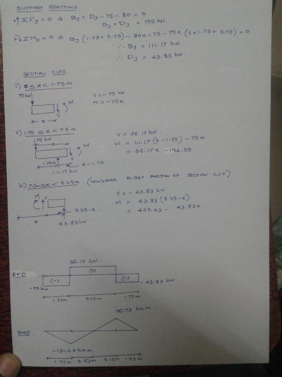
QUESTION 1 [15] For the simply supported beam subjected to the loading shown in the figure,...
 QUESTION 1 [15] For the simply supported beam subjected to the loading shown in the figure, a) Derive equations for the shear force V and the bending moment M for any location in the beam. (Place the origin at point A.) b) Report the maximum positive bending moment, the maximum negative bending moment, and their respective locations. 36 KN 180 KN-m X B C D 4 m 5 m 3 m Figure 1
Draw the shear force and bending-moment diagrams for the simply supported beam shown. Label each diagram...
 Draw the shear force and bending-moment diagrams for the simply
supported beam shown. Label each diagram with the corresponding
values
1. Draw the shear force and bending-moment diagrams for the simply supported beam shown. Label each diagram with the corresponding values. 3 Pe= 30 KN 4 m - m 3 m - C -40 kN - m
Draw the shear force and bending-moment diagrams for the simply
supported beam shown. Label each diagram with the corresponding
values
1. Draw the shear force and bending-moment diagrams for the simply supported beam shown. Label each diagram with the corresponding values. 3 Pe= 30 KN 4 m - m 3 m - C -40 kN - m
a simply supported beam abcd with arectangular cross sectioncarries the loading shown in figure. the...
 a simply supported beam abcd with arectangular cross section
carries the loading shown in figure. the uniform beam has a mass of
33 kg per meter (m kg/m) and a cross section as shown in the
figure. you may take 10 m/s^2 as acceleration.Question A2 A simply supported beam ABCD with a rectangular cross-section carries the loading shown in Figure QA2. The uniform beam has a mass of m kg per meter of length (m kg/m) and a cross-section as shown...
a simply supported beam abcd with arectangular cross section
carries the loading shown in figure. the uniform beam has a mass of
33 kg per meter (m kg/m) and a cross section as shown in the
figure. you may take 10 m/s^2 as acceleration.Question A2 A simply supported beam ABCD with a rectangular cross-section carries the loading shown in Figure QA2. The uniform beam has a mass of m kg per meter of length (m kg/m) and a cross-section as shown...
If a simply supported beam is subjected to the following loading and across section of the beam is provided
If a simply supported beam is subjected to the following loading and across section of the beam is provided, determine the following a. Determine the maximum bending stress in the beam. b. Determine the absolute maximum shear stress in the beam.
The beam AC is simply supported at A and C and subjected to the uniformly distributed...
 The beam AC is simply supported at A and C and subjected to the uniformly distributed load of q=300 N/m plus the couple of magnitude M=2700 N·mas shown. Draw shearing force and bending moment diagrams of the beam. Show all the work leading to the diagrams. [35 marks] q L D B CO -3m-1-3----3m--
 *Part 1 For the simply supported beam subjected to the loading shown, derive equations for the shear force V and the bending moment M for any location in the beam. (Place the origin at point A.) Let a-3.00 m, b=4.00 m, Pg - 35kN, and Pc = 90kN. Construct the shear-force and bending-moment diagrams on paper and use the results to answer the questions in the subsequent parts of this GO exercise. Calculate the reaction forces Ay and Dy acting...
 1. For the simply supported beam subjected to the loading shown, Derive equations for the shear force V and the bending moment M for any location in the beam. (Place the origin at point A.) a. b. Plot the shear-force and bending-moment diagrams for the beam using the derived functions c. Report the maximum bending moment and its location. 42 kips 6 kips/ft 10 ft 20 ft
 Part 1 For the simply supported beam subfected to the loading shown, derive equations for the shear force V and the bending moment M for any location in the beam. (Place the origin at point A.) Let a-13.0 ft, b-5.0 ft, c-3.0 ft, w -9 kips/tt and M-160 kip-ft. Construct the shear-force and bending-murnent ??durams on paper and use?ie 'esults to answer the uuestions in the subsequent parts of this GO exertise. Calculate the reactian farces Ay and Cy acting...
 Shear force and bending moments of the beam.
For the simply supported beam subjected to the loading shown in Figure P7.8 derive equations for the shear force V and the bending moment M for any location in the beam. (Place the origin at point A.) plot the shear-force and bending-moment diagrams for the beam, using the derived functions. report the maximum positive bending moment, the maximum negative bending moment, and their respective locations.
Shear force and bending moments of the beam.
For the simply supported beam subjected to the loading shown in Figure P7.8 derive equations for the shear force V and the bending moment M for any location in the beam. (Place the origin at point A.) plot the shear-force and bending-moment diagrams for the beam, using the derived functions. report the maximum positive bending moment, the maximum negative bending moment, and their respective locations.
 QUESTION 1 [15] For the simply supported beam subjected to the loading shown in the figure, a) Derive equations for the shear force V and the bending moment M for any location in the beam. (Place the origin at point A.) b) Report the maximum positive bending moment, the maximum negative bending moment, and their respective locations. 36 KN 180 KN-m X B C D 4 m 5 m 3 m Figure 1
 Draw the shear force and bending-moment diagrams for the simply
supported beam shown. Label each diagram with the corresponding
values
1. Draw the shear force and bending-moment diagrams for the simply supported beam shown. Label each diagram with the corresponding values. 3 Pe= 30 KN 4 m - m 3 m - C -40 kN - m
Draw the shear force and bending-moment diagrams for the simply
supported beam shown. Label each diagram with the corresponding
values
1. Draw the shear force and bending-moment diagrams for the simply supported beam shown. Label each diagram with the corresponding values. 3 Pe= 30 KN 4 m - m 3 m - C -40 kN - m
 a simply supported beam abcd with arectangular cross section
carries the loading shown in figure. the uniform beam has a mass of
33 kg per meter (m kg/m) and a cross section as shown in the
figure. you may take 10 m/s^2 as acceleration.Question A2 A simply supported beam ABCD with a rectangular cross-section carries the loading shown in Figure QA2. The uniform beam has a mass of m kg per meter of length (m kg/m) and a cross-section as shown...
a simply supported beam abcd with arectangular cross section
carries the loading shown in figure. the uniform beam has a mass of
33 kg per meter (m kg/m) and a cross section as shown in the
figure. you may take 10 m/s^2 as acceleration.Question A2 A simply supported beam ABCD with a rectangular cross-section carries the loading shown in Figure QA2. The uniform beam has a mass of m kg per meter of length (m kg/m) and a cross-section as shown...
 The beam AC is simply supported at A and C and subjected to the uniformly distributed load of q=300 N/m plus the couple of magnitude M=2700 N·mas shown. Draw shearing force and bending moment diagrams of the beam. Show all the work leading to the diagrams. [35 marks] q L D B CO -3m-1-3----3m--
Most questions answered within 3 hours.
-
What specific indicators can point to lack of progress for
African Americans in American society?
asked 11 minutes ago -
1-The Electrons in a beam are moving at 2.7×10⁸ m/s in an
electric field of 15000...
asked 27 minutes ago -
A gas tank is a vertical cylinder. It has a radius of 1m, a
height of...
asked 53 minutes ago -
Accent Software faces the following conditions. All of these
support Accent’s use of a market-penetration pricing...
asked 1 hour ago -
A mathematically inclined friend emails you the following
instructions: "Meet me in the cafeteria the first...
asked 1 hour ago -
A monopoly sells in two countries . The demand curves in the two
countries are p1...
asked 2 hours ago -
A .15kg rubber ball is bounced off a wall. Before hitting the
wall, the ball moves...
asked 3 hours ago -
A manufacturing company preparing to build a new plant is
considering three potential locations for it....
asked 3 hours ago -
B. If compound Y has approximately the same values of solubility
in toluene as compound X,...
asked 4 hours ago -
Oscar Inc. has inventory in Japan valued at 39,051,000 Yen one
year ago. One year ago...
asked 4 hours ago -
If Canada suffered from "fundamental disequilibrium," and its
government choose not to devalue its currency, a...
asked 4 hours ago -
4. How many input & output Key Value Pairs are passed into,
and emitted out of...
asked 4 hours ago