1) Check stability and determinacy of the structure 2) draw free body diagram 3) determine reactions...

1) Check stability and determinacy of the structure
2) draw free body diagram
3) determine reactions
4) draw shear diagram
- correct values
- correct shape
- location of the maximum moment on member BC
5) draw moment diagram
- correct values
- correct shape
- location of the maximum moment on member BC
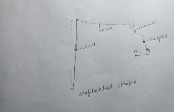
6) draw deformation shape
Homework Answers


Add Answer to:
1) Check stability and determinacy of the structure
2) draw free body diagram
3) determine reactions...
beam problem QUESTION 6: Draw the free body diagram of the beam shown below and determine...
 beam problem
QUESTION 6: Draw the free body diagram of the beam shown below and determine the reactions and formulate the shear-force and bending moment equations for the beam. Sketch the shear and moment diagrams: Type your answers and intermediate calculations on the screen on the blackboard 400 N 100 N/m A 4 m 4 m
beam problem
QUESTION 6: Draw the free body diagram of the beam shown below and determine the reactions and formulate the shear-force and bending moment equations for the beam. Sketch the shear and moment diagrams: Type your answers and intermediate calculations on the screen on the blackboard 400 N 100 N/m A 4 m 4 m
a. Draw a complete free-body diagram for the beam shown in Fig. 1. Must show and...
 a. Draw a complete free-body diagram for the beam shown in Fig.
1. Must show and label x-y coordinate system, support reactions,
loads, and dimensions
b. Derive formulas for all support reactions using conditions of
equilibrium. Must show all work.
c. Using the student variables shown below, calculate beam
support reactions and draw shear and bending moment diagrams. To
receive full credit, support reactions and loads must be shown on a
free-body diagram. Each shear and bending moment diagram must...
a. Draw a complete free-body diagram for the beam shown in Fig.
1. Must show and label x-y coordinate system, support reactions,
loads, and dimensions
b. Derive formulas for all support reactions using conditions of
equilibrium. Must show all work.
c. Using the student variables shown below, calculate beam
support reactions and draw shear and bending moment diagrams. To
receive full credit, support reactions and loads must be shown on a
free-body diagram. Each shear and bending moment diagram must...
Question 3:: Draw the free body diagram and calculate the reactions. Determine the internal normal force,...
 Question 3:: Draw the free body diagram and calculate the reactions. Determine the internal normal force, shear force, and moments at points C. Point A is a cantilever support. Type your answers and intermediate calculations on the screen on the blackboard. tokw rrm 6
draw the free body diagram and determine the reactions
 draw the free body diagram and determine the reactions
2. (a) Draw a free body diagram for member ABC shown below. (b) Determine the reactions...
 2. (a) Draw a free body diagram for member ABC shown below. (b) Determine the reactions at the supports A and C. P = 10 kN and a = 1 m. Begin your solution on this page 30
E = 200 GPa Draw the free body diagram showing the load and the reactions at...
 E = 200 GPa
Draw the free body diagram showing the load and the reactions at
the support, the shear force diagram, and the bending moment
diagram
у P х 2.5 m 100 mm 7 7 150 mm
E = 200 GPa
Draw the free body diagram showing the load and the reactions at
the support, the shear force diagram, and the bending moment
diagram
у P х 2.5 m 100 mm 7 7 150 mm
Draw a free-body diagram of the segment 8≤x<14 m where x is in meters on paper....
 Draw a free-body diagram of the segment 8≤x<14 m
where x is in meters on paper. Write expressions for the
internal shear, V, and moment, M,
over this segment. (the answer requires x)
Learning Goal: To determine all of the reactive forces and moments acting on a beam, express the shear and bending moment as functions of their positions along the beam, and construct shear and bending moment diagrams. The cantilever beam shown is subjected to a moment at A...
Draw a free-body diagram of the segment 8≤x<14 m
where x is in meters on paper. Write expressions for the
internal shear, V, and moment, M,
over this segment. (the answer requires x)
Learning Goal: To determine all of the reactive forces and moments acting on a beam, express the shear and bending moment as functions of their positions along the beam, and construct shear and bending moment diagrams. The cantilever beam shown is subjected to a moment at A...
For the two frames given below Compute the Support Reactions Draw the Free Body Diagrams for...
 For the two frames given below Compute the Support Reactions Draw the Free Body Diagrams for all members, and joints with concentrated load or moment Draw the Bending Moment Diagram, Shear Force Diagram, and Axial Force Diagram using the sign conventions and labeling scheme taught in the class Draw the Qualitative Deflected Shape, clearly showing the Inflection Points, if any. 1. (50 points) 45 k Need FBD 3 k/ft 15 ft 2. (50 points) 15 kN/m F G 65 kN...
PROBLEM 3 (25%) For the problem shown below, the free body diagram (FBD) is superimposed showing...
 PROBLEM 3 (25%) For the problem shown below, the free body diagram (FBD) is superimposed showing the reactions forces (the reaction forces are given). Ax = 0; Ay = 9 kip, Cy = 33 kip 1. Draw the shear force diagram. Identify values at kink points (no equations required). 2. Draw the bending moment diagram. Identify values at kink points (no equations required). 3. Determine the value of the maximum positive moment in the beam (Mmax). 4. Compute the vertical...
 beam problem
QUESTION 6: Draw the free body diagram of the beam shown below and determine the reactions and formulate the shear-force and bending moment equations for the beam. Sketch the shear and moment diagrams: Type your answers and intermediate calculations on the screen on the blackboard 400 N 100 N/m A 4 m 4 m
beam problem
QUESTION 6: Draw the free body diagram of the beam shown below and determine the reactions and formulate the shear-force and bending moment equations for the beam. Sketch the shear and moment diagrams: Type your answers and intermediate calculations on the screen on the blackboard 400 N 100 N/m A 4 m 4 m
 a. Draw a complete free-body diagram for the beam shown in Fig.
1. Must show and label x-y coordinate system, support reactions,
loads, and dimensions
b. Derive formulas for all support reactions using conditions of
equilibrium. Must show all work.
c. Using the student variables shown below, calculate beam
support reactions and draw shear and bending moment diagrams. To
receive full credit, support reactions and loads must be shown on a
free-body diagram. Each shear and bending moment diagram must...
a. Draw a complete free-body diagram for the beam shown in Fig.
1. Must show and label x-y coordinate system, support reactions,
loads, and dimensions
b. Derive formulas for all support reactions using conditions of
equilibrium. Must show all work.
c. Using the student variables shown below, calculate beam
support reactions and draw shear and bending moment diagrams. To
receive full credit, support reactions and loads must be shown on a
free-body diagram. Each shear and bending moment diagram must...
 Question 3:: Draw the free body diagram and calculate the reactions. Determine the internal normal force, shear force, and moments at points C. Point A is a cantilever support. Type your answers and intermediate calculations on the screen on the blackboard. tokw rrm 6
 2. (a) Draw a free body diagram for member ABC shown below. (b) Determine the reactions at the supports A and C. P = 10 kN and a = 1 m. Begin your solution on this page 30
 E = 200 GPa
Draw the free body diagram showing the load and the reactions at
the support, the shear force diagram, and the bending moment
diagram
у P х 2.5 m 100 mm 7 7 150 mm
E = 200 GPa
Draw the free body diagram showing the load and the reactions at
the support, the shear force diagram, and the bending moment
diagram
у P х 2.5 m 100 mm 7 7 150 mm
 Draw a free-body diagram of the segment 8≤x<14 m
where x is in meters on paper. Write expressions for the
internal shear, V, and moment, M,
over this segment. (the answer requires x)
Learning Goal: To determine all of the reactive forces and moments acting on a beam, express the shear and bending moment as functions of their positions along the beam, and construct shear and bending moment diagrams. The cantilever beam shown is subjected to a moment at A...
Draw a free-body diagram of the segment 8≤x<14 m
where x is in meters on paper. Write expressions for the
internal shear, V, and moment, M,
over this segment. (the answer requires x)
Learning Goal: To determine all of the reactive forces and moments acting on a beam, express the shear and bending moment as functions of their positions along the beam, and construct shear and bending moment diagrams. The cantilever beam shown is subjected to a moment at A...
 For the two frames given below Compute the Support Reactions Draw the Free Body Diagrams for all members, and joints with concentrated load or moment Draw the Bending Moment Diagram, Shear Force Diagram, and Axial Force Diagram using the sign conventions and labeling scheme taught in the class Draw the Qualitative Deflected Shape, clearly showing the Inflection Points, if any. 1. (50 points) 45 k Need FBD 3 k/ft 15 ft 2. (50 points) 15 kN/m F G 65 kN...
 PROBLEM 3 (25%) For the problem shown below, the free body diagram (FBD) is superimposed showing the reactions forces (the reaction forces are given). Ax = 0; Ay = 9 kip, Cy = 33 kip 1. Draw the shear force diagram. Identify values at kink points (no equations required). 2. Draw the bending moment diagram. Identify values at kink points (no equations required). 3. Determine the value of the maximum positive moment in the beam (Mmax). 4. Compute the vertical...
 PROBLEM 3 (25%) For the problem shown below, the free body diagram (FBD) is superimposed showing the reactions forces (the reaction forces are given). Ax = 0; Ay = 9 kip, Cy = 33 kip 1. Draw the shear force diagram. Identify values at kink points (no equations required). 2. Draw the bending moment diagram. Identify values at kink points (no equations required). 3. Determine the value of the maximum positive moment in the beam (Mmax). 4. Compute the vertical...
Most questions answered within 3 hours.
-
(Expected rate of return and risk) Carter Inc. is evaluating a
security. Calculate the investment’s expected...
asked 2 hours ago -
What specific indicators can point to lack of progress for
African Americans in American society?
asked 3 hours ago -
1-The Electrons in a beam are moving at 2.7×10⁸ m/s in an
electric field of 15000...
asked 3 hours ago -
A gas tank is a vertical cylinder. It has a radius of 1m, a
height of...
asked 4 hours ago -
Accent Software faces the following conditions. All of these
support Accent’s use of a market-penetration pricing...
asked 5 hours ago -
A mathematically inclined friend emails you the following
instructions: "Meet me in the cafeteria the first...
asked 5 hours ago -
A monopoly sells in two countries . The demand curves in the two
countries are p1...
asked 6 hours ago -
A .15kg rubber ball is bounced off a wall. Before hitting the
wall, the ball moves...
asked 6 hours ago -
A manufacturing company preparing to build a new plant is
considering three potential locations for it....
asked 6 hours ago -
B. If compound Y has approximately the same values of solubility
in toluene as compound X,...
asked 7 hours ago -
Oscar Inc. has inventory in Japan valued at 39,051,000 Yen one
year ago. One year ago...
asked 7 hours ago -
If Canada suffered from "fundamental disequilibrium," and its
government choose not to devalue its currency, a...
asked 7 hours ago