

Homework Answers

Add Answer to:
what is the answer for 9.51?
Fig. P9.50 the i of and 125 mm+125 mm as...
Find the total couple of the system in vector unit i, j and k Fig. P3.78...
 Find the total couple of the system in vector unit i, j and k Fig. P3.78 160 mm 120 mm 50 N 144 min 120 mm E 19.5 N 192 mm 125 N
5 mm 10 mm 1000 mm I 90 mm Fig. 1: A hollow shaft with a...
 5 mm 10 mm 1000 mm I 90 mm Fig. 1: A hollow shaft with a solid circular disc Question 1 For the system shown in Fig. 1, a vertical hollow steel shaft of diameter (d) = 5mm and length (L) = 100mm is fixed at its upper end and has a solid circular disc having a diameter (D) = 90mm and a mass (m) 12kg fixed rigidly to its lower end as shown. Taking G = 83 GN/m2 for...
How to calculate the plastic hinge depth of the following I section beam? Dimensions are in mm 200 25 125 500 25 200 25 125 500 25
 How
to calculate the plastic hinge depth of the following I section
beam? Dimensions are in mm
200 25 125 500 25
200 25 125 500 25
How
to calculate the plastic hinge depth of the following I section
beam? Dimensions are in mm
200 25 125 500 25
200 25 125 500 25
12.7 Express in terms of Y, for the I-section beam in Fig. 12.37, the bending moment to cause yielding throughout the depth of the flanges and throughout the whole section. Also establish the plasti...
 12.7 Express in terms of Y, for the I-section beam in Fig. 12.37, the bending moment to cause yielding throughout the depth of the flanges and throughout the whole section. Also establish the plastic penetration depth for an applied moment of 850 kNm with Y 278 MPa. Answer: 45.3Y, 48.6Y (kNm), 100 mm. 200 25 500 125 25
12.7 Express in terms of Y, for the I-section beam in Fig. 12.37, the bending moment to cause yielding throughout the depth...
12.7 Express in terms of Y, for the I-section beam in Fig. 12.37, the bending moment to cause yielding throughout the depth of the flanges and throughout the whole section. Also establish the plastic penetration depth for an applied moment of 850 kNm with Y 278 MPa. Answer: 45.3Y, 48.6Y (kNm), 100 mm. 200 25 500 125 25
12.7 Express in terms of Y, for the I-section beam in Fig. 12.37, the bending moment to cause yielding throughout the depth...
S0 mm 170 mm 125 mm ? 75mm 4. Determine the components of the reactions at...
 S0 mm 170 mm 125 mm ? 75mm 4. Determine the components of the reactions at A and E if the frame is loaded by a clockwise couple of magnitude 78 N m applied at B 2 Ib L s of the reaction at E are: Ex lb t O Type here to search
8) Given: bar of brass alloy with ơ- diagram given in Fig. 6.12. a-25 mm, b-80...
 8) Given: bar of brass alloy with ơ- diagram given in Fig. 6.12. a-25 mm, b-80 mm, L-200 a) F-200 kN is applied. What is the final length of the bar AFTER the force is released? b) F-800 kN is applied. What is the final length of the bar AFTER the force is released?
C- A physical system consists of two parts (electrical and rotational mechanical) shown in Fig.1. It...
 C- A physical system consists of two parts (electrical and rotational mechanical) shown in Fig.1. It d0 has the following relations. K3w, friction coefficient b , TL =KiI, eb = K2w, w= dt i-Find a mathematical model and Laplace model? (2) ii- Draw a control block diagram and find e(S)/E(S)? L (5) Ro) Es ww S) He "L Fig.2 Fig.1
C- A physical system consists of two parts (electrical and rotational mechanical) shown in Fig.1. It d0 has the following...
C- A physical system consists of two parts (electrical and rotational mechanical) shown in Fig.1. It d0 has the following relations. K3w, friction coefficient b , TL =KiI, eb = K2w, w= dt i-Find a mathematical model and Laplace model? (2) ii- Draw a control block diagram and find e(S)/E(S)? L (5) Ro) Es ww S) He "L Fig.2 Fig.1
C- A physical system consists of two parts (electrical and rotational mechanical) shown in Fig.1. It d0 has the following...
1. The maximum deflection for the beam given below is 3.5 mm. E = 125 x...
 1. The maximum deflection for the beam given below is 3.5 mm. E = 125 x 10' MPa and I = 85,000 mm". Calculate the load (W). A B RA 2m
Q1 9 Fig.1 Cross sectional area of the core is 5 cm2. N-100, i) Draw flux linkage current characteristics of the device shown in Fig. 1 for g- 3 mm and lmm ii) What is the energy stored in this c...
 Q1 9 Fig.1 Cross sectional area of the core is 5 cm2. N-100, i) Draw flux linkage current characteristics of the device shown in Fig. 1 for g- 3 mm and lmm ii) What is the energy stored in this core for i 10 A iii) What is the coenergy stored for 1-10 A iii) Derive an expression for the inductance of the coil. v) What is the inductance of the coil? vi) Calculate the average force on the armature...
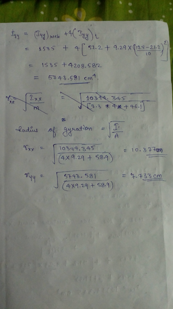
Marks 1 An angle bean (Fig. I) is used as a roof purlin. span of Am distributed load of 8 kN/m on a simply suppo...
 Marks 1 An angle bean (Fig. I) is used as a roof purlin. span of Am distributed load of 8 kN/m on a simply supporte scomers n the roof is l:5, compute the flexural stresses at tie 4.08x Take l 11.56x 100 mm, 1,420x10 mm, l shear centre a 2 For the thin walled beam section (Fir It carries a vertical uniformly span of 4m. If the slope of ers A, B and C escription 6 ses at the c...
 Find the total couple of the system in vector unit i, j and k Fig. P3.78 160 mm 120 mm 50 N 144 min 120 mm E 19.5 N 192 mm 125 N
 5 mm 10 mm 1000 mm I 90 mm Fig. 1: A hollow shaft with a solid circular disc Question 1 For the system shown in Fig. 1, a vertical hollow steel shaft of diameter (d) = 5mm and length (L) = 100mm is fixed at its upper end and has a solid circular disc having a diameter (D) = 90mm and a mass (m) 12kg fixed rigidly to its lower end as shown. Taking G = 83 GN/m2 for...
 How
to calculate the plastic hinge depth of the following I section
beam? Dimensions are in mm
200 25 125 500 25
200 25 125 500 25
How
to calculate the plastic hinge depth of the following I section
beam? Dimensions are in mm
200 25 125 500 25
200 25 125 500 25
 12.7 Express in terms of Y, for the I-section beam in Fig. 12.37, the bending moment to cause yielding throughout the depth of the flanges and throughout the whole section. Also establish the plastic penetration depth for an applied moment of 850 kNm with Y 278 MPa. Answer: 45.3Y, 48.6Y (kNm), 100 mm. 200 25 500 125 25
12.7 Express in terms of Y, for the I-section beam in Fig. 12.37, the bending moment to cause yielding throughout the depth...
12.7 Express in terms of Y, for the I-section beam in Fig. 12.37, the bending moment to cause yielding throughout the depth of the flanges and throughout the whole section. Also establish the plastic penetration depth for an applied moment of 850 kNm with Y 278 MPa. Answer: 45.3Y, 48.6Y (kNm), 100 mm. 200 25 500 125 25
12.7 Express in terms of Y, for the I-section beam in Fig. 12.37, the bending moment to cause yielding throughout the depth...
 S0 mm 170 mm 125 mm ? 75mm 4. Determine the components of the reactions at A and E if the frame is loaded by a clockwise couple of magnitude 78 N m applied at B 2 Ib L s of the reaction at E are: Ex lb t O Type here to search
 8) Given: bar of brass alloy with ơ- diagram given in Fig. 6.12. a-25 mm, b-80 mm, L-200 a) F-200 kN is applied. What is the final length of the bar AFTER the force is released? b) F-800 kN is applied. What is the final length of the bar AFTER the force is released?
 C- A physical system consists of two parts (electrical and rotational mechanical) shown in Fig.1. It d0 has the following relations. K3w, friction coefficient b , TL =KiI, eb = K2w, w= dt i-Find a mathematical model and Laplace model? (2) ii- Draw a control block diagram and find e(S)/E(S)? L (5) Ro) Es ww S) He "L Fig.2 Fig.1
C- A physical system consists of two parts (electrical and rotational mechanical) shown in Fig.1. It d0 has the following...
C- A physical system consists of two parts (electrical and rotational mechanical) shown in Fig.1. It d0 has the following relations. K3w, friction coefficient b , TL =KiI, eb = K2w, w= dt i-Find a mathematical model and Laplace model? (2) ii- Draw a control block diagram and find e(S)/E(S)? L (5) Ro) Es ww S) He "L Fig.2 Fig.1
C- A physical system consists of two parts (electrical and rotational mechanical) shown in Fig.1. It d0 has the following...
 1. The maximum deflection for the beam given below is 3.5 mm. E = 125 x 10' MPa and I = 85,000 mm". Calculate the load (W). A B RA 2m
 Q1 9 Fig.1 Cross sectional area of the core is 5 cm2. N-100, i) Draw flux linkage current characteristics of the device shown in Fig. 1 for g- 3 mm and lmm ii) What is the energy stored in this core for i 10 A iii) What is the coenergy stored for 1-10 A iii) Derive an expression for the inductance of the coil. v) What is the inductance of the coil? vi) Calculate the average force on the armature...
 Marks 1 An angle bean (Fig. I) is used as a roof purlin. span of Am distributed load of 8 kN/m on a simply supporte scomers n the roof is l:5, compute the flexural stresses at tie 4.08x Take l 11.56x 100 mm, 1,420x10 mm, l shear centre a 2 For the thin walled beam section (Fir It carries a vertical uniformly span of 4m. If the slope of ers A, B and C escription 6 ses at the c...
Most questions answered within 3 hours.
-
An MNE is this kind of industry when competition in one country
is essentially independent of...
asked 44 minutes ago -
. For this set of questions, determine what
proportion of a normal distribution is located betweeneach...
asked 1 hour ago -
A college student is employed as a door-to-door newspaper
salesman. Historical data suggests that the student...
asked 2 hours ago -
MATLAB HW 11 problem using Switch Case and Input commands
Write a script file that calculates...
asked 1 hour ago -
Considering gravitational time dilation, calculate the time that
passes in Earth’s surface while 1 hour passes...
asked 2 hours ago -
Minitab Problem: Take the Lake Hume June rainfall data and find
use the processes outlined in...
asked 3 hours ago -
X Company is trying to decide whether to continue using old
equipment to make Product A...
asked 3 hours ago -
IN PYTHON ONLY !! Program 2: Re-work
program #5 (WeeklyHours) from the previous assignment such that...
asked 4 hours ago -
The average length of time between arrivals at a turnpike
toll-booth is 26 seconds. What is...
asked 5 hours ago -
(a) A piston at 6.1 atm contains a gas that occupies a volume of
3.5 L....
asked 7 hours ago -
Please answer true or false. Words
cannot be changed or added in to make it true...
asked 6 hours ago -
An empty test tube weighs 15.923 grams. Then,
MgCl2•6H2O is added into the test tube. After...
asked 7 hours ago