
Homework Answers
Add Answer to:
Consider the circuit shown in (Figure 1). Suppose that v1 = 12 V and U2 =...
Problem 4.7 Consider the circuit shown in (Figure 1). The source voltage v1 is 40 V....
 Problem 4.7 Consider the circuit shown in (Figure 1). The source voltage v1 is 40 V. Resistance R1, R2 and R3 are 5 ,120 and 15 , respectively. The source current I is 25 mA Part A Find the power developed by the current source I in the circuit. Express your answer to three significant figures and include the appropriate units. НА Value Units Рi 3 Request Answer Submit Part B Figure 1 of 1 Find the power developed by...
Problem 4.32 Consider the circuit shown in (Figure 1). Use the mesh- current method to find...
 Problem 4.32 Consider the circuit shown in (Figure 1). Use the mesh- current method to find the branch currents ia - ze in the circuit. Take v1 = 32 V and ug = 2 V. Part A Find in Express your answer to three significant figures and include the appropriate units. HÅ ? Value Units Submit Previous Answers Request Answer X Incorrect; Try Again; 3 attempts remaining Part B Find is. Express your answer to three significant figures and include...
\ Problem 6 Consider the circuit shown in (Figure 1). Suppose that V, = 480_0°V (rms)....
 \
Problem 6 Consider the circuit shown in (Figure 1). Suppose that V, = 480_0°V (rms). Part A Find the average power dissipated in the line in the figure Express your answer three significant figures and include the appropriate units. HHA ? P = Value Units Submit Request Answer Part B Figure 1 of 1 > Find the capacitive reactance that, when connected in parallel, with the load will make the load look purely resistive. Express your answer three significant...
\
Problem 6 Consider the circuit shown in (Figure 1). Suppose that V, = 480_0°V (rms). Part A Find the average power dissipated in the line in the figure Express your answer three significant figures and include the appropriate units. HHA ? P = Value Units Submit Request Answer Part B Figure 1 of 1 > Find the capacitive reactance that, when connected in parallel, with the load will make the load look purely resistive. Express your answer three significant...
Please answer all parts Consider the circuit shown in (Figure 1). Suppose that Ve = 50070°V...
 Please answer all parts
Consider the circuit shown in (Figure 1). Suppose that Ve = 50070°V (rms). Express your answer to three significant figures and include the appropriate units. View Available Hint(s) IT HA ? 21 = Value Units Submit Part D Find the average power dissipated in the line when the capacitive reactance is connected across the load. Express your answer to three significant figures and include the appropriate units. THA th ? P- Value Units Submit Request Answer...
Please answer all parts
Consider the circuit shown in (Figure 1). Suppose that Ve = 50070°V (rms). Express your answer to three significant figures and include the appropriate units. View Available Hint(s) IT HA ? 21 = Value Units Submit Part D Find the average power dissipated in the line when the capacitive reactance is connected across the load. Express your answer to three significant figures and include the appropriate units. THA th ? P- Value Units Submit Request Answer...
Constants Part A Consider the circuit shown in (Figure 1). Suppose that 9 kΩ Find the...
 Constants Part A Consider the circuit shown in (Figure 1). Suppose that 9 kΩ Find the current i in the circuit by making a succession of appropriate source transformations Express your answer to three significant figures and include the appropriate units i,Value Units Submit Request Answer Figure 1 of 1 Part B Work back through the circuit to find the magnitude of the power developed by the 120 V source Express your answer to three significant figures and include the...
Problem 4.51 7 of 9 > Review Constants Consider the circuit in(Figure 1). Suppose that v1...
 Problem 4.51 7 of 9 > Review Constants Consider the circuit in(Figure 1). Suppose that v1 = 45 V.03 = 81 V, and is = 3.6 A. Part A Find the total power dissipated in the circuit. Express your answer to three significant figures and include the appropriate units. Pliss = 842 W Submit Previous Answers Correct Part B Find the total power dissipated if the 3.6 A current source is replaced by a short circuit. Express your answer to...
Consider the circuit shown in (Figure 1). Suppose that Vg = 125 cos 250 V 80...
 Consider the circuit shown in (Figure 1). Suppose that Vg = 125 cos 250 V 80 uF 50 Ω ug +1 3100 mH Load Find the average power absorbed by the load in the circuit. Use positive value if the power is absorbed and negative value if the power is delivered. Express your answer to three significant figures and include the appropriate units. View Available Hint(s) ID μΑ PR ? P = Value Units Find the reactive power absorbed by...
P 2.28 l Review ▼ Part A Consider the circuit shown in (Figure 1). Suppose that...
 P 2.28 l Review ▼ Part A Consider the circuit shown in (Figure 1). Suppose that i 3.2A Find the value of u, Express your answer to three significant figures and include the appropriate u CB Figure く 1of1 Value Units v,- Submit 30Ω 6 0 Part B 100 12 Find the value of Part B Find the value of v1 Express your answer to three significant figures and include the appropriate units. vValue Units 01F Submit Request Answer Part...
Please answer showing detailed work. PartA Consider the circuit shown in (Figure 1). Suppose that k...
 Please answer showing detailed work.
PartA Consider the circuit shown in (Figure 1). Suppose that k 135 and V 180 V Use the mesh-current method to calculate the power delivered by the dependent voltage source Express your answer to three significant figures and include the appropriate units Figure 1 of 1 .1 Value Units Paelratue Submit 10Ω 30Ω ki, Provide Feedback 20Ω
Please answer showing detailed work.
PartA Consider the circuit shown in (Figure 1). Suppose that k 135 and V 180 V Use the mesh-current method to calculate the power delivered by the dependent voltage source Express your answer to three significant figures and include the appropriate units Figure 1 of 1 .1 Value Units Paelratue Submit 10Ω 30Ω ki, Provide Feedback 20Ω
Consider the circuit shown in . Suppose that us = 34 V. ξ2.5 kΩ Part A...
 Consider the circuit shown in . Suppose that us = 34 V. ξ2.5 kΩ Part A Find i for the circuit. Express your answer to three significant figures and include the appropriate units. iz Value Units Part B Find the power supplied by the voltage source. Express your answer to three significant figures and include the appropriate units. HAR O ? Value Units Part C Reverse the polarity of the voltage source in the circuit shown in the figure, and...
 Problem 4.7 Consider the circuit shown in (Figure 1). The source voltage v1 is 40 V. Resistance R1, R2 and R3 are 5 ,120 and 15 , respectively. The source current I is 25 mA Part A Find the power developed by the current source I in the circuit. Express your answer to three significant figures and include the appropriate units. НА Value Units Рi 3 Request Answer Submit Part B Figure 1 of 1 Find the power developed by...
 Problem 4.32 Consider the circuit shown in (Figure 1). Use the mesh- current method to find the branch currents ia - ze in the circuit. Take v1 = 32 V and ug = 2 V. Part A Find in Express your answer to three significant figures and include the appropriate units. HÅ ? Value Units Submit Previous Answers Request Answer X Incorrect; Try Again; 3 attempts remaining Part B Find is. Express your answer to three significant figures and include...
 \
Problem 6 Consider the circuit shown in (Figure 1). Suppose that V, = 480_0°V (rms). Part A Find the average power dissipated in the line in the figure Express your answer three significant figures and include the appropriate units. HHA ? P = Value Units Submit Request Answer Part B Figure 1 of 1 > Find the capacitive reactance that, when connected in parallel, with the load will make the load look purely resistive. Express your answer three significant...
\
Problem 6 Consider the circuit shown in (Figure 1). Suppose that V, = 480_0°V (rms). Part A Find the average power dissipated in the line in the figure Express your answer three significant figures and include the appropriate units. HHA ? P = Value Units Submit Request Answer Part B Figure 1 of 1 > Find the capacitive reactance that, when connected in parallel, with the load will make the load look purely resistive. Express your answer three significant...
 Please answer all parts
Consider the circuit shown in (Figure 1). Suppose that Ve = 50070°V (rms). Express your answer to three significant figures and include the appropriate units. View Available Hint(s) IT HA ? 21 = Value Units Submit Part D Find the average power dissipated in the line when the capacitive reactance is connected across the load. Express your answer to three significant figures and include the appropriate units. THA th ? P- Value Units Submit Request Answer...
Please answer all parts
Consider the circuit shown in (Figure 1). Suppose that Ve = 50070°V (rms). Express your answer to three significant figures and include the appropriate units. View Available Hint(s) IT HA ? 21 = Value Units Submit Part D Find the average power dissipated in the line when the capacitive reactance is connected across the load. Express your answer to three significant figures and include the appropriate units. THA th ? P- Value Units Submit Request Answer...
 Constants Part A Consider the circuit shown in (Figure 1). Suppose that 9 kΩ Find the current i in the circuit by making a succession of appropriate source transformations Express your answer to three significant figures and include the appropriate units i,Value Units Submit Request Answer Figure 1 of 1 Part B Work back through the circuit to find the magnitude of the power developed by the 120 V source Express your answer to three significant figures and include the...
 Problem 4.51 7 of 9 > Review Constants Consider the circuit in(Figure 1). Suppose that v1 = 45 V.03 = 81 V, and is = 3.6 A. Part A Find the total power dissipated in the circuit. Express your answer to three significant figures and include the appropriate units. Pliss = 842 W Submit Previous Answers Correct Part B Find the total power dissipated if the 3.6 A current source is replaced by a short circuit. Express your answer to...
 Consider the circuit shown in (Figure 1). Suppose that Vg = 125 cos 250 V 80 uF 50 Ω ug +1 3100 mH Load Find the average power absorbed by the load in the circuit. Use positive value if the power is absorbed and negative value if the power is delivered. Express your answer to three significant figures and include the appropriate units. View Available Hint(s) ID μΑ PR ? P = Value Units Find the reactive power absorbed by...
 P 2.28 l Review ▼ Part A Consider the circuit shown in (Figure 1). Suppose that i 3.2A Find the value of u, Express your answer to three significant figures and include the appropriate u CB Figure く 1of1 Value Units v,- Submit 30Ω 6 0 Part B 100 12 Find the value of Part B Find the value of v1 Express your answer to three significant figures and include the appropriate units. vValue Units 01F Submit Request Answer Part...
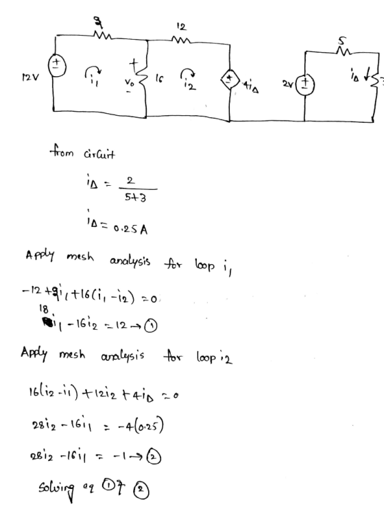
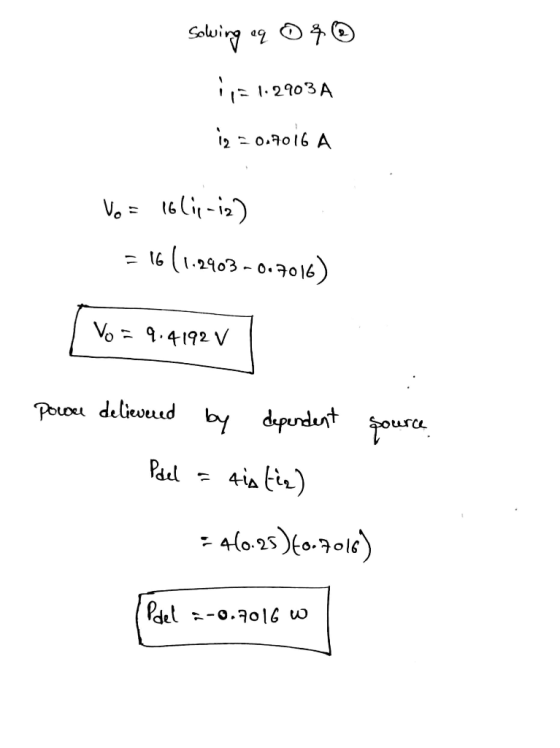
 Please answer showing detailed work.
PartA Consider the circuit shown in (Figure 1). Suppose that k 135 and V 180 V Use the mesh-current method to calculate the power delivered by the dependent voltage source Express your answer to three significant figures and include the appropriate units Figure 1 of 1 .1 Value Units Paelratue Submit 10Ω 30Ω ki, Provide Feedback 20Ω
Please answer showing detailed work.
PartA Consider the circuit shown in (Figure 1). Suppose that k 135 and V 180 V Use the mesh-current method to calculate the power delivered by the dependent voltage source Express your answer to three significant figures and include the appropriate units Figure 1 of 1 .1 Value Units Paelratue Submit 10Ω 30Ω ki, Provide Feedback 20Ω
 Consider the circuit shown in . Suppose that us = 34 V. ξ2.5 kΩ Part A Find i for the circuit. Express your answer to three significant figures and include the appropriate units. iz Value Units Part B Find the power supplied by the voltage source. Express your answer to three significant figures and include the appropriate units. HAR O ? Value Units Part C Reverse the polarity of the voltage source in the circuit shown in the figure, and...
Most questions answered within 3 hours.
-
(63
#14)
which of the following statments best describes how chamging
the concentration of the substances...
asked 46 minutes ago -
In the following reaction, which element is undergoing
oxidation: Na2SO3 + N2O --> N2 + Na2SO4...
asked 1 hour ago -
Which of the following pairs of ions have the same electron
configuration?
I: Br− and Se2−...
asked 4 hours ago -
The Foremost Composite Materials Company is planning a two-day
sales conference for October 19-20. The conference...
asked 4 hours ago -
3) Illustrate the observed pattern of relatedness of organisms
versus adaptations to specific conditions. This means...
asked 4 hours ago -
In winter a lake has a 0.35 m thick ice layer over 1.10 m of
water....
asked 5 hours ago -
Assuming the following has been encrypted with a Vigenere cipher
below, use the method(s) and assumptions...
asked 6 hours ago -
How would I use switch statements to write a program that will
take an input of...
asked 6 hours ago -
Imagine a reaction in which methane gas combusts at a constant
pressure of 1 atm and...
asked 6 hours ago -
Two parallel wires (each 12 m in length) are separated by a
distance of 0.065 m...
asked 6 hours ago -
Suppose there were three masses at the corner of uniform
equilateral triangle. The masses are m1...
asked 6 hours ago -
Situation: A building that is 618 m above the ground floor. How
many times would a...
asked 6 hours ago