 Both questions please. Please use NVL and show steps.
Homework Answers


Add Answer to:
Both questions please. Please use NVL and show steps.
2) Use he deuoltag mehod to fnd...
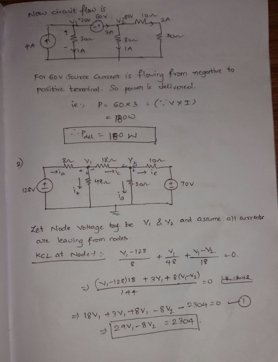
2) Use the circuit below to determine the following: a. Use mesh curre b. Use node-voltage...
 2) Use the circuit below to determine the following: a. Use mesh curre b. Use node-voltage to verify the currents i,- ie from part a. (10 pts) c. Show that th nt to find the branch currents for i,- ie for the circuit shown (10 pts) e total power developed in the circuit equals the total power consumed by the circuit. (5 pts) 5? 102 19 A 40 23ia 2 lb 240 V
*****Use R = 8 ohms********** Please answer both questions a and b. R Q 0.1 H...
 *****Use R = 8 ohms**********
Please answer both questions a and b.
R Q 0.1 H 100 V 1 mF HE + 30%) Find the value wo .The circuit above shows a RLC series circuit that are connected LC across the voltage source 100 V rms AC. a) By hand solve: For the value of wo find voltages and currents in L,C,R, power and power factor at the source. Scan your work and upload to D2L b) For different values...
*****Use R = 8 ohms**********
Please answer both questions a and b.
R Q 0.1 H 100 V 1 mF HE + 30%) Find the value wo .The circuit above shows a RLC series circuit that are connected LC across the voltage source 100 V rms AC. a) By hand solve: For the value of wo find voltages and currents in L,C,R, power and power factor at the source. Scan your work and upload to D2L b) For different values...
problem 2 please Problem 2 (50 points) Consider the circuit below and answer the following questions:...
 problem 2 please
Problem 2 (50 points) Consider the circuit below and answer the following questions: R,-4Ω +Vi 2 V a- [20 Points] Using nodal analysis method, find the voltages VA. VB. Ve and Vo b [12 Points] Calculate the currents I and Is. c- 8 Points] Calculate the voltage Vs across the dependent current source. d- [10 Points] Calculate the power absorbed delivered by each voltage source in the circuit
problem 2 please
Problem 2 (50 points) Consider the circuit below and answer the following questions: R,-4Ω +Vi 2 V a- [20 Points] Using nodal analysis method, find the voltages VA. VB. Ve and Vo b [12 Points] Calculate the currents I and Is. c- 8 Points] Calculate the voltage Vs across the dependent current source. d- [10 Points] Calculate the power absorbed delivered by each voltage source in the circuit
please do all parts of both questions thanks 5. (10 points) For the circuit shown in...
 please do all parts of both questions thanks
5. (10 points) For the circuit shown in Figure 2, compute the voltage across the load terminals. *Tip: use KVL 0.19 0.52 1 = 60/A 120/0° v VLOND LOAD Figure 2. Circuit for problem 5. 6. (15 points) A 60-Hz, single-phase source with V = 277230°volts is applied to a circuit element (a) Determine the instantaneous source voltage (b) Also determine the phasor and instantaneous currents entering the positive terminal if the...
please do all parts of both questions thanks
5. (10 points) For the circuit shown in Figure 2, compute the voltage across the load terminals. *Tip: use KVL 0.19 0.52 1 = 60/A 120/0° v VLOND LOAD Figure 2. Circuit for problem 5. 6. (15 points) A 60-Hz, single-phase source with V = 277230°volts is applied to a circuit element (a) Determine the instantaneous source voltage (b) Also determine the phasor and instantaneous currents entering the positive terminal if the...
I need tge calculation only not the design. please show the steps A location in the...
 I need tge calculation only not the design. please show the
steps
A location in the power system can be modeled by the circuit in Figure 1. The line is modeled as a resistor and the load is modeled by a series resistance and inductance. The systems details are as follows: vs(t) =Scos(628.32t + Bv.) V (Set the AC voltage source to output this voltage) RUINE 150 RLOAD 330 L 0.4H i(t) ect . + LINE ROAD vs(t) LOAD ВЈЕ...
I need tge calculation only not the design. please show the
steps
A location in the power system can be modeled by the circuit in Figure 1. The line is modeled as a resistor and the load is modeled by a series resistance and inductance. The systems details are as follows: vs(t) =Scos(628.32t + Bv.) V (Set the AC voltage source to output this voltage) RUINE 150 RLOAD 330 L 0.4H i(t) ect . + LINE ROAD vs(t) LOAD ВЈЕ...
PLEASE SHOW ALL WORK AND TO FOLLOW DIRECTIONS. PLEASE USE PSPICE. STUDENT ID= 7220849 2. Using...
 PLEASE SHOW ALL WORK AND TO FOLLOW DIRECTIONS. PLEASE USE
PSPICE.
STUDENT ID= 7220849
2. Using a DC Sweep analysis to generate a table of values in the .OUT file: See Circuit 2 below: Let R1 through R6 equivalent to the digits 1 through 6 in your StudentID in k12 (use 10 k22 for a digit of 0). • For example, if your StudentID is 9870654 then R1 =9 kN, R2 =8 kN, R3 = 7kN, R4 = 10KN, R5...
PLEASE SHOW ALL WORK AND TO FOLLOW DIRECTIONS. PLEASE USE
PSPICE.
STUDENT ID= 7220849
2. Using a DC Sweep analysis to generate a table of values in the .OUT file: See Circuit 2 below: Let R1 through R6 equivalent to the digits 1 through 6 in your StudentID in k12 (use 10 k22 for a digit of 0). • For example, if your StudentID is 9870654 then R1 =9 kN, R2 =8 kN, R3 = 7kN, R4 = 10KN, R5...
Please do parts b-d. 2. Consider the circuit shown below. 0.2i 7 2 4Ω 1Ω 4Ω 0.1 va (a) By hand, use any method (node voltage, mesh currents, etc.) tosolve for the currentix b) Using Spice, solve for...
 Please do parts b-d.
2. Consider the circuit shown below. 0.2i 7 2 4Ω 1Ω 4Ω 0.1 va (a) By hand, use any method (node voltage, mesh currents, etc.) tosolve for the currentix b) Using Spice, solve for ix and compare with your hand calculation. (c) Plot Va vs. Vs, where Vs replaces the 9 V voltage source (and has the same polarity) and varies from -20 to 20 volts. At what value of Vs does the direction of the...
Please do parts b-d.
2. Consider the circuit shown below. 0.2i 7 2 4Ω 1Ω 4Ω 0.1 va (a) By hand, use any method (node voltage, mesh currents, etc.) tosolve for the currentix b) Using Spice, solve for ix and compare with your hand calculation. (c) Plot Va vs. Vs, where Vs replaces the 9 V voltage source (and has the same polarity) and varies from -20 to 20 volts. At what value of Vs does the direction of the...
The program has to be written in C The expected output: Please make sure to use...
 The program has to be written in C
The expected output:
Please make sure to use two-dimensional
arrays.
OPTIONAL TAKE-HOME QUIZ WORTH 10 POINTS OUT OF A GRAND TOTAL OF 110 FOR THE COURSE A DC electrical circuit consists of an ideal battery with user-suppled terminal voltage VB which drives a resistive load comprised of a user-supplied number m of branches connected in parallel across each other, with each branch consisting of a variable user-supplied number n of resistors and...
The program has to be written in C
The expected output:
Please make sure to use two-dimensional
arrays.
OPTIONAL TAKE-HOME QUIZ WORTH 10 POINTS OUT OF A GRAND TOTAL OF 110 FOR THE COURSE A DC electrical circuit consists of an ideal battery with user-suppled terminal voltage VB which drives a resistive load comprised of a user-supplied number m of branches connected in parallel across each other, with each branch consisting of a variable user-supplied number n of resistors and...
Please show all of the steps Question 2: 20% We can use stack of diodes as...
 Please show all of the steps
Question 2: 20% We can use stack of diodes as a voltage regulator as shown in the circuit below. Consider input voltage to this circuit as 20V DC with IV of fluctuation. Diodes in this circuit have 0.7V forward voltage drop a) What is DC output voltage Vo? 20+1V Vo= 1.4 V R=1k2 b) What is diode DC current lo? Ip= 18-6 ma c) What is the value of individual diode's small-signal resistor/? (4%)...
Please show all of the steps
Question 2: 20% We can use stack of diodes as a voltage regulator as shown in the circuit below. Consider input voltage to this circuit as 20V DC with IV of fluctuation. Diodes in this circuit have 0.7V forward voltage drop a) What is DC output voltage Vo? 20+1V Vo= 1.4 V R=1k2 b) What is diode DC current lo? Ip= 18-6 ma c) What is the value of individual diode's small-signal resistor/? (4%)...
PLEASE SHOW ALL WORK AND TO FOLLOW DIRECTIONS. PLEASE USE PSPICE. STUDENT ID= 7220849 3. Using...
 PLEASE SHOW ALL WORK AND TO FOLLOW DIRECTIONS. PLEASE USE
PSPICE.
STUDENT ID= 7220849
3. Using a DC Sweep analysis to graph currents and voltages Let R1 through R4 equivalent to the digits 1 through 4 in your StudentID in k 2 (use 10 k12 for a digit of 0). • For example, if your StudentID is 9870654 then R1 =9 KS2, R2 =8 kN, R3 = 7k2 and R4 = 10k12 A. Analyze Circuit 3 by hand to determine...
PLEASE SHOW ALL WORK AND TO FOLLOW DIRECTIONS. PLEASE USE
PSPICE.
STUDENT ID= 7220849
3. Using a DC Sweep analysis to graph currents and voltages Let R1 through R4 equivalent to the digits 1 through 4 in your StudentID in k 2 (use 10 k12 for a digit of 0). • For example, if your StudentID is 9870654 then R1 =9 KS2, R2 =8 kN, R3 = 7k2 and R4 = 10k12 A. Analyze Circuit 3 by hand to determine...
 2) Use the circuit below to determine the following: a. Use mesh curre b. Use node-voltage to verify the currents i,- ie from part a. (10 pts) c. Show that th nt to find the branch currents for i,- ie for the circuit shown (10 pts) e total power developed in the circuit equals the total power consumed by the circuit. (5 pts) 5? 102 19 A 40 23ia 2 lb 240 V
 *****Use R = 8 ohms**********
Please answer both questions a and b.
R Q 0.1 H 100 V 1 mF HE + 30%) Find the value wo .The circuit above shows a RLC series circuit that are connected LC across the voltage source 100 V rms AC. a) By hand solve: For the value of wo find voltages and currents in L,C,R, power and power factor at the source. Scan your work and upload to D2L b) For different values...
*****Use R = 8 ohms**********
Please answer both questions a and b.
R Q 0.1 H 100 V 1 mF HE + 30%) Find the value wo .The circuit above shows a RLC series circuit that are connected LC across the voltage source 100 V rms AC. a) By hand solve: For the value of wo find voltages and currents in L,C,R, power and power factor at the source. Scan your work and upload to D2L b) For different values...
 problem 2 please
Problem 2 (50 points) Consider the circuit below and answer the following questions: R,-4Ω +Vi 2 V a- [20 Points] Using nodal analysis method, find the voltages VA. VB. Ve and Vo b [12 Points] Calculate the currents I and Is. c- 8 Points] Calculate the voltage Vs across the dependent current source. d- [10 Points] Calculate the power absorbed delivered by each voltage source in the circuit
problem 2 please
Problem 2 (50 points) Consider the circuit below and answer the following questions: R,-4Ω +Vi 2 V a- [20 Points] Using nodal analysis method, find the voltages VA. VB. Ve and Vo b [12 Points] Calculate the currents I and Is. c- 8 Points] Calculate the voltage Vs across the dependent current source. d- [10 Points] Calculate the power absorbed delivered by each voltage source in the circuit
 please do all parts of both questions thanks
5. (10 points) For the circuit shown in Figure 2, compute the voltage across the load terminals. *Tip: use KVL 0.19 0.52 1 = 60/A 120/0° v VLOND LOAD Figure 2. Circuit for problem 5. 6. (15 points) A 60-Hz, single-phase source with V = 277230°volts is applied to a circuit element (a) Determine the instantaneous source voltage (b) Also determine the phasor and instantaneous currents entering the positive terminal if the...
please do all parts of both questions thanks
5. (10 points) For the circuit shown in Figure 2, compute the voltage across the load terminals. *Tip: use KVL 0.19 0.52 1 = 60/A 120/0° v VLOND LOAD Figure 2. Circuit for problem 5. 6. (15 points) A 60-Hz, single-phase source with V = 277230°volts is applied to a circuit element (a) Determine the instantaneous source voltage (b) Also determine the phasor and instantaneous currents entering the positive terminal if the...
 I need tge calculation only not the design. please show the
steps
A location in the power system can be modeled by the circuit in Figure 1. The line is modeled as a resistor and the load is modeled by a series resistance and inductance. The systems details are as follows: vs(t) =Scos(628.32t + Bv.) V (Set the AC voltage source to output this voltage) RUINE 150 RLOAD 330 L 0.4H i(t) ect . + LINE ROAD vs(t) LOAD ВЈЕ...
I need tge calculation only not the design. please show the
steps
A location in the power system can be modeled by the circuit in Figure 1. The line is modeled as a resistor and the load is modeled by a series resistance and inductance. The systems details are as follows: vs(t) =Scos(628.32t + Bv.) V (Set the AC voltage source to output this voltage) RUINE 150 RLOAD 330 L 0.4H i(t) ect . + LINE ROAD vs(t) LOAD ВЈЕ...
 PLEASE SHOW ALL WORK AND TO FOLLOW DIRECTIONS. PLEASE USE
PSPICE.
STUDENT ID= 7220849
2. Using a DC Sweep analysis to generate a table of values in the .OUT file: See Circuit 2 below: Let R1 through R6 equivalent to the digits 1 through 6 in your StudentID in k12 (use 10 k22 for a digit of 0). • For example, if your StudentID is 9870654 then R1 =9 kN, R2 =8 kN, R3 = 7kN, R4 = 10KN, R5...
PLEASE SHOW ALL WORK AND TO FOLLOW DIRECTIONS. PLEASE USE
PSPICE.
STUDENT ID= 7220849
2. Using a DC Sweep analysis to generate a table of values in the .OUT file: See Circuit 2 below: Let R1 through R6 equivalent to the digits 1 through 6 in your StudentID in k12 (use 10 k22 for a digit of 0). • For example, if your StudentID is 9870654 then R1 =9 kN, R2 =8 kN, R3 = 7kN, R4 = 10KN, R5...
 Please do parts b-d.
2. Consider the circuit shown below. 0.2i 7 2 4Ω 1Ω 4Ω 0.1 va (a) By hand, use any method (node voltage, mesh currents, etc.) tosolve for the currentix b) Using Spice, solve for ix and compare with your hand calculation. (c) Plot Va vs. Vs, where Vs replaces the 9 V voltage source (and has the same polarity) and varies from -20 to 20 volts. At what value of Vs does the direction of the...
Please do parts b-d.
2. Consider the circuit shown below. 0.2i 7 2 4Ω 1Ω 4Ω 0.1 va (a) By hand, use any method (node voltage, mesh currents, etc.) tosolve for the currentix b) Using Spice, solve for ix and compare with your hand calculation. (c) Plot Va vs. Vs, where Vs replaces the 9 V voltage source (and has the same polarity) and varies from -20 to 20 volts. At what value of Vs does the direction of the...
 The program has to be written in C
The expected output:
Please make sure to use two-dimensional
arrays.
OPTIONAL TAKE-HOME QUIZ WORTH 10 POINTS OUT OF A GRAND TOTAL OF 110 FOR THE COURSE A DC electrical circuit consists of an ideal battery with user-suppled terminal voltage VB which drives a resistive load comprised of a user-supplied number m of branches connected in parallel across each other, with each branch consisting of a variable user-supplied number n of resistors and...
The program has to be written in C
The expected output:
Please make sure to use two-dimensional
arrays.
OPTIONAL TAKE-HOME QUIZ WORTH 10 POINTS OUT OF A GRAND TOTAL OF 110 FOR THE COURSE A DC electrical circuit consists of an ideal battery with user-suppled terminal voltage VB which drives a resistive load comprised of a user-supplied number m of branches connected in parallel across each other, with each branch consisting of a variable user-supplied number n of resistors and...
 Please show all of the steps
Question 2: 20% We can use stack of diodes as a voltage regulator as shown in the circuit below. Consider input voltage to this circuit as 20V DC with IV of fluctuation. Diodes in this circuit have 0.7V forward voltage drop a) What is DC output voltage Vo? 20+1V Vo= 1.4 V R=1k2 b) What is diode DC current lo? Ip= 18-6 ma c) What is the value of individual diode's small-signal resistor/? (4%)...
Please show all of the steps
Question 2: 20% We can use stack of diodes as a voltage regulator as shown in the circuit below. Consider input voltage to this circuit as 20V DC with IV of fluctuation. Diodes in this circuit have 0.7V forward voltage drop a) What is DC output voltage Vo? 20+1V Vo= 1.4 V R=1k2 b) What is diode DC current lo? Ip= 18-6 ma c) What is the value of individual diode's small-signal resistor/? (4%)...
 PLEASE SHOW ALL WORK AND TO FOLLOW DIRECTIONS. PLEASE USE
PSPICE.
STUDENT ID= 7220849
3. Using a DC Sweep analysis to graph currents and voltages Let R1 through R4 equivalent to the digits 1 through 4 in your StudentID in k 2 (use 10 k12 for a digit of 0). • For example, if your StudentID is 9870654 then R1 =9 KS2, R2 =8 kN, R3 = 7k2 and R4 = 10k12 A. Analyze Circuit 3 by hand to determine...
PLEASE SHOW ALL WORK AND TO FOLLOW DIRECTIONS. PLEASE USE
PSPICE.
STUDENT ID= 7220849
3. Using a DC Sweep analysis to graph currents and voltages Let R1 through R4 equivalent to the digits 1 through 4 in your StudentID in k 2 (use 10 k12 for a digit of 0). • For example, if your StudentID is 9870654 then R1 =9 KS2, R2 =8 kN, R3 = 7k2 and R4 = 10k12 A. Analyze Circuit 3 by hand to determine...
Most questions answered within 3 hours.
-
284 mL of a 0.52 M potassium hydroxide solution is added to 467
mL of a...
asked 3 minutes ago -
exercise on VSEPR and molecular structrue.
octahedral
SeCl62-
TeCl62-
ClF62-
distorted
SeF62–
IF6–
asked 4 minutes ago -
Little’s Law: Val d’Costa is a world famous ski village in the
French Alps. Because of...
asked 56 minutes ago -
Find the absolute error D for the calculation if A + B/C=D A=
9.4 +/- 0.4...
asked 1 hour ago -
New Air Heating and Cooling, manufactures furnaces and central
air units. The company pride itself on...
asked 1 hour ago -
A coach uses a new technique to train gymnasts. Seven
gymnasts were randomly selected and their...
asked 3 hours ago -
While rotating the tires on your car you notice a rock [mass =
0.1 Kg] stuck...
asked 5 hours ago -
Using MARS simulator, write MIPS programs according to
the following scenarios: Receive a positive integer number...
asked 7 hours ago -
An object in front of a concave mirror has a real image that is
11.5 cm...
asked 7 hours ago -
Consider the reaction, C3 H8 + O2 --> CO2 + H2O. How many
moles of O2...
asked 9 hours ago -
You and your opponent both roll a fair die. If you both roll the
same number,...
asked 9 hours ago -
In a study of the accuracy of fast food drive-through orders,
Restaurant A had 257 accurate...
asked 9 hours ago