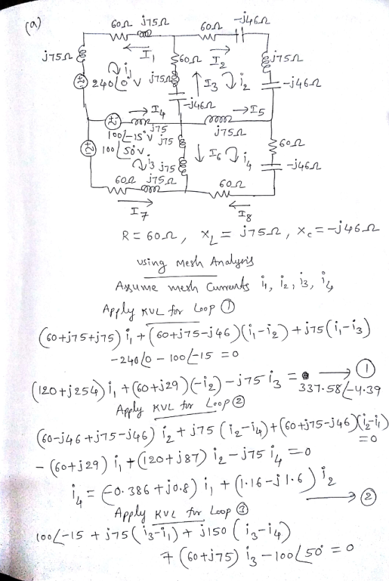
Each resistor, inductor, and capacitor has 60 ohms, 75 ohms, and 46 ohms respectively. Calculate the...

Homework Answers
![-375 I 305, 94/18-69 t3 2 づ7512-J 150 13 + (ine.jm)k-o 11 ‘ tja. 1,地14.314) 1] 12.0+ 13: 1.276181.92., +2.86 97-94 ן2](http://img.homeworklib.com/questions/07e1b620-a7b2-11eb-9a89-3f596c263570.png?x-oss-process=image/resize,w_560)


Add Answer to:
Each resistor, inductor, and capacitor has 60 ohms, 75 ohms,
and 46 ohms respectively. Calculate the...
Calculate the voltage in the capacitor and the current in the inductor of the circuit, calculate...
 Calculate the voltage in the capacitor and the current in the
inductor of the circuit, calculate the reactive power (Q), active
(P) of the circuit and the total apparent power (S), which power
factor is in the circuit.
0.5 H M 50 cos(10+ 30°) 6 1012 Z +v
Calculate the voltage in the capacitor and the current in the
inductor of the circuit, calculate the reactive power (Q), active
(P) of the circuit and the total apparent power (S), which power
factor is in the circuit.
0.5 H M 50 cos(10+ 30°) 6 1012 Z +v
Figure 2.6 depicts this circuit as a voltage source applied to a resistor and inductor in...
 Figure 2.6 depicts this circuit as a voltage source applied to a
resistor and inductor in parallel (disregard the capacitor for part
A), which is to be an equivalent to the load. Why is a
resistor and inductor in parallel used for the load versus just
using a resistor?
Find the following (show calculations):
Real power absorbed by the load.
Apparent power of the load.
Reactive power of the load. Don’t use the tangent
function. Instead, find the reactive power using the
apparent...
Figure 2.6 depicts this circuit as a voltage source applied to a
resistor and inductor in parallel (disregard the capacitor for part
A), which is to be an equivalent to the load. Why is a
resistor and inductor in parallel used for the load versus just
using a resistor?
Find the following (show calculations):
Real power absorbed by the load.
Apparent power of the load.
Reactive power of the load. Don’t use the tangent
function. Instead, find the reactive power using the
apparent...
An inductor, a resistor, and a capacitor are in series (see figure below) with a 60...
 An inductor, a resistor, and a capacitor are in series (see
figure below) with a 60 cycle source of ac. The inductor has self
inductance of 0.5 H and resistance of 20Ω. The resistor has 80Ω of
resistance and capacitor has 8 µF of capacitance. What is the
impedance of the circuit? (b) What is the power factor? (C) Find
the resonancefrequency of the circuit.
50.2 LOME Q11 An inductor, a resistor, and a capacitor are in series (see figure...
An inductor, a resistor, and a capacitor are in series (see
figure below) with a 60 cycle source of ac. The inductor has self
inductance of 0.5 H and resistance of 20Ω. The resistor has 80Ω of
resistance and capacitor has 8 µF of capacitance. What is the
impedance of the circuit? (b) What is the power factor? (C) Find
the resonancefrequency of the circuit.
50.2 LOME Q11 An inductor, a resistor, and a capacitor are in series (see figure...
. A 250-ohm resistor, a 0.450 H inductor, and a 6.45 F capacitor are connected in...
. A 250-ohm resistor, a 0.450 H inductor, and a 6.45 F capacitor are connected in series across an emf with a 36.0 volt amplitude and an angular frequency of 260 rad/s. a. What is the impedance? b. What is the current amplitude? c. What is the phase angle between the voltage and current? Does the voltage lag or lead? d. What are the voltage amplitudes across the resistor, inductor and capacitor individually? e. What is the power? f. What...
1) Use the circuit to the right. f = 12kHz 10V 20° 50mH 1.2k 47nF a)...
 1) Use the circuit to the right. f = 12kHz 10V 20° 50mH 1.2k 47nF a) (10pts) Find the average (real) power of the resistor. b) (10pts) Find the average (real) power of the capacitor. c) (10pts) Find the average (real) power of the inductor. (10pts) Find the total average (real) power of the circuit. f) (10pts) Find the reactive power of the capacitor. g) (10pts) Find the reactive power of the inductor. h) (10pts) Find the total reactive power...
#3. A 250-ohm resistor, a 0.450 H inductor, and a 6.45 uF capacitor are connected in...
#3. A 250-ohm resistor, a 0.450 H inductor, and a 6.45 uF capacitor are connected in series across an emf with a 36.0 volt amplitude and an angular frequency of 260 rad/s. a. What is the impedance? b. What is the current amplitude? c. What is the phase angle between the voltage and current? Does the voltage lag or lead? d. What are the voltage amplitudes across the resistor, inductor and capacitor individually? e. What is the power? f. What...
a. b. C. A 250-ohm resistor, a 0.450 H inductor, and a 6.45 uF capacitor are...
 a. b. C. A 250-ohm resistor, a 0.450 H inductor, and a 6.45 uF capacitor are connected in series across an emf with a 36.0 volt amplitude and an angular frequency of 260 rad/s. What is the impedance? What is the current amplitude? What is the phase angle between the voltage and current? Does the voltage lag or lead? What are the voltage amplitudes across the resistor, inductor and capacitor individually? What is the power? f. What is the resonant...
All missing parts please. (7%) Problem 6: A 16-Ω resistor, 45-uF capacitor, and 3.5-mH inductor are...
 All missing parts please.
(7%) Problem 6: A 16-Ω resistor, 45-uF capacitor, and 3.5-mH inductor are connected in series with an AC source of amplitude 13 V and frequency 135 Hz. 8% Part (a) What is the impedance of the circuit, in ohms? 8% Part (b) What is the amplitude of the current in the circuit, in amperes? 8% Part (c) What is the phase constant of the current, in degrees? 8% Part (d) With a source voltage of Vsourc,-Vocos(2π...
All missing parts please.
(7%) Problem 6: A 16-Ω resistor, 45-uF capacitor, and 3.5-mH inductor are connected in series with an AC source of amplitude 13 V and frequency 135 Hz. 8% Part (a) What is the impedance of the circuit, in ohms? 8% Part (b) What is the amplitude of the current in the circuit, in amperes? 8% Part (c) What is the phase constant of the current, in degrees? 8% Part (d) With a source voltage of Vsourc,-Vocos(2π...
4) An RLC circuit consists of a resistor, a inductor, and a capacitor connected in series to an A...
4) An RLC circuit consists of a resistor, a inductor, and a capacitor connected in series to an AC voltage source with an RMS voltage of 59 volts. At half the resonant frequency, the phase angle is -35 degrees and the inductive reactance is 46 Ohms. What is the average dissipated power at twice the resonant frequency in Watts?
6. In the below figure, a single phase system, with a frequency of 60 Hz is...
 6. In the below figure, a single phase system, with a frequency of 60 Hz is connected acrossa resistor and an inductor. Find the expression for v(t). What is the rms value of current through 30 resistor? 3Ω Find expression for the current i(t). What is the power factor? Find the power dissipated in the 3Ω resistor. Find the reactive power Q. Find the apparent power. To get a unity power factor a capacitor is connected across the source. Find...
 Calculate the voltage in the capacitor and the current in the
inductor of the circuit, calculate the reactive power (Q), active
(P) of the circuit and the total apparent power (S), which power
factor is in the circuit.
0.5 H M 50 cos(10+ 30°) 6 1012 Z +v
Calculate the voltage in the capacitor and the current in the
inductor of the circuit, calculate the reactive power (Q), active
(P) of the circuit and the total apparent power (S), which power
factor is in the circuit.
0.5 H M 50 cos(10+ 30°) 6 1012 Z +v
 Figure 2.6 depicts this circuit as a voltage source applied to a
resistor and inductor in parallel (disregard the capacitor for part
A), which is to be an equivalent to the load. Why is a
resistor and inductor in parallel used for the load versus just
using a resistor?
Find the following (show calculations):
Real power absorbed by the load.
Apparent power of the load.
Reactive power of the load. Don’t use the tangent
function. Instead, find the reactive power using the
apparent...
Figure 2.6 depicts this circuit as a voltage source applied to a
resistor and inductor in parallel (disregard the capacitor for part
A), which is to be an equivalent to the load. Why is a
resistor and inductor in parallel used for the load versus just
using a resistor?
Find the following (show calculations):
Real power absorbed by the load.
Apparent power of the load.
Reactive power of the load. Don’t use the tangent
function. Instead, find the reactive power using the
apparent...
 An inductor, a resistor, and a capacitor are in series (see
figure below) with a 60 cycle source of ac. The inductor has self
inductance of 0.5 H and resistance of 20Ω. The resistor has 80Ω of
resistance and capacitor has 8 µF of capacitance. What is the
impedance of the circuit? (b) What is the power factor? (C) Find
the resonancefrequency of the circuit.
50.2 LOME Q11 An inductor, a resistor, and a capacitor are in series (see figure...
An inductor, a resistor, and a capacitor are in series (see
figure below) with a 60 cycle source of ac. The inductor has self
inductance of 0.5 H and resistance of 20Ω. The resistor has 80Ω of
resistance and capacitor has 8 µF of capacitance. What is the
impedance of the circuit? (b) What is the power factor? (C) Find
the resonancefrequency of the circuit.
50.2 LOME Q11 An inductor, a resistor, and a capacitor are in series (see figure...
 1) Use the circuit to the right. f = 12kHz 10V 20° 50mH 1.2k 47nF a) (10pts) Find the average (real) power of the resistor. b) (10pts) Find the average (real) power of the capacitor. c) (10pts) Find the average (real) power of the inductor. (10pts) Find the total average (real) power of the circuit. f) (10pts) Find the reactive power of the capacitor. g) (10pts) Find the reactive power of the inductor. h) (10pts) Find the total reactive power...
 a. b. C. A 250-ohm resistor, a 0.450 H inductor, and a 6.45 uF capacitor are connected in series across an emf with a 36.0 volt amplitude and an angular frequency of 260 rad/s. What is the impedance? What is the current amplitude? What is the phase angle between the voltage and current? Does the voltage lag or lead? What are the voltage amplitudes across the resistor, inductor and capacitor individually? What is the power? f. What is the resonant...
 All missing parts please.
(7%) Problem 6: A 16-Ω resistor, 45-uF capacitor, and 3.5-mH inductor are connected in series with an AC source of amplitude 13 V and frequency 135 Hz. 8% Part (a) What is the impedance of the circuit, in ohms? 8% Part (b) What is the amplitude of the current in the circuit, in amperes? 8% Part (c) What is the phase constant of the current, in degrees? 8% Part (d) With a source voltage of Vsourc,-Vocos(2π...
All missing parts please.
(7%) Problem 6: A 16-Ω resistor, 45-uF capacitor, and 3.5-mH inductor are connected in series with an AC source of amplitude 13 V and frequency 135 Hz. 8% Part (a) What is the impedance of the circuit, in ohms? 8% Part (b) What is the amplitude of the current in the circuit, in amperes? 8% Part (c) What is the phase constant of the current, in degrees? 8% Part (d) With a source voltage of Vsourc,-Vocos(2π...
 6. In the below figure, a single phase system, with a frequency of 60 Hz is connected acrossa resistor and an inductor. Find the expression for v(t). What is the rms value of current through 30 resistor? 3Ω Find expression for the current i(t). What is the power factor? Find the power dissipated in the 3Ω resistor. Find the reactive power Q. Find the apparent power. To get a unity power factor a capacitor is connected across the source. Find...
Most questions answered within 3 hours.
-
Calculate the number density of argon gas at a temperature of
24C and a pressure of...
asked 2 hours ago -
Alternative
Classification
How to Estimate
Probabilities from Data? ( For continuous Attributes)
And How to generate...
asked 2 hours ago -
An explosion breaks a 20.0-kg object into three parts. The
object is initially moving at a...
asked 3 hours ago -
Calculate the approximate number of residues of Rubisco, which
is involved in carbon fixation in plants,...
asked 4 hours ago -
Other decisions about scientific claims can have a much broader
impact.ENERGYarrow-10x10.png, environment, health, security - all...
asked 5 hours ago -
I need to write a research paper and work cited about this
topic: The United States...
asked 6 hours ago -
Hello! I was wondering if I could have some help?
If the vapor pressure of carvone...
asked 6 hours ago -
An economist wants to estimate the mean per capita income (in
thousands of dollars) for a...
asked 6 hours ago -
What would be the input/output characteristic of a circuit
obtained by putting two of your 2's-complementers...
asked 6 hours ago -
In Drosophila, the transition from the syncytial blastoderm
stage to the cellular blastoderm stage is a...
asked 7 hours ago -
Project management question:
Name 3 different types of resources (hint: humans are one
type)
asked 7 hours ago -
Consider the following reaction: C 2H 2( g) + 2H 2( g) C 2H 6(
g)...
asked 7 hours ago