Take C1= 5.00 uF, C2= 10.00 uF, and C3= 2.00 uF

Use the numbers given for C1, C2 and C3, (and V later on).
Redraw the circuits as needed.
For the top part:
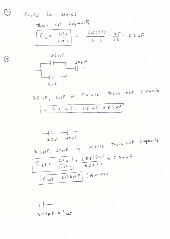
a) For C1 and C2 on the left upper side, find Cleq, (series).
b) For C1 and C2 on the right upper side, find Creq, (series).
Redrawing the top part, will now have 3 Cs (Cleq, C3, and Creq) in parallel. This is in series with the lower part. Call this circuit 2.
c) Find the Cteq for these 3 capacitors.
Now for the bottom part:
d) The 2 C2s are connected in parallel. Find Cbeq.
Now, redraw this circuit, with the top part, Cteq, (part c) and the bottom part, Cbeq, (part d) in series. Call this circuit 3.
Homework Answers
Add Answer to:
Take C1= 5.00 uF, C2= 10.00 uF, and C3= 2.00 uF
Use the numbers given for...
If C1= 10 uF C2= 20 uF C3 =30 uF C4=40 uF C5= 50uF C6= 60uF....
If C1= 10 uF C2= 20 uF C3 =30 uF C4=40 uF C5= 50uF C6= 60uF. Calculate the equivalent capacitance of C1, C2 , C3, and ,C5 all in parallel. Also calculate with ALL the capacitors is series calculate V2 and Q2 assuming that Vab =20 volts across the entire circuit.
The C1 -2.0 uF and 3.0 uF capacitor equivalent capacitance is X1-5.0 μF. Likewise, the C2-3.0...
 The C1 -2.0 uF and 3.0 uF capacitor equivalent capacitance is X1-5.0 μF. Likewise, the C2-3.0 μF and 6.0 μF capacitors are also in parallel and have an equivalent capacitance of Y1-9.0屹The upper branch in Figure 26.11b now consists of a 4.0 μF capacitor and a 5.0 μF In series, which combine to give x2 according to the following equation. rs are in parallel and combine according to Ceq C1+C2. Their Likewise, the lower branch in Figure 26.11b consists of...
In this circuit, C1=10μF, C2=12 μF, and C3=15 μF. The voltage across the batteries is 20V....
 In this circuit, C1=10μF, C2=12 μF, and C3=15 μF. The voltage
across the batteries is 20V.
a. Find the voltage across each capacitor and the charge on each
one.
b. These three capacitors are replaced by two equal capacitors
in parallel. What should the capacitance of these two capacitors be
for the two circuits to be equivalent?
C1 C2 C3
In this circuit, C1=10μF, C2=12 μF, and C3=15 μF. The voltage
across the batteries is 20V.
a. Find the voltage across each capacitor and the charge on each
one.
b. These three capacitors are replaced by two equal capacitors
in parallel. What should the capacitance of these two capacitors be
for the two circuits to be equivalent?
C1 C2 C3
C1 C2 Problem 3. Capacitors in series and in parallel. Switches. = = S2 C3 C4...
 C1 C2 Problem 3. Capacitors in series and in parallel. Switches. = = S2 C3 C4 In this circuit, C1=1 uF, C2=2 uF, C3=3 uF, and C4=4 uF. The voltage source is an ideal 12 V battery. Find the charge on each capacitor when: a) Only Si is closed (obligatory) b) Si and S2 are both closed (extra, highly recommended for practice) S, 11 C1 C2 = = Extra space C1=1 uF, C2=2 uF, C3=3 uF, C4=4 uF, ε =12...
3. You are given three capacitors C1 10.0 uF, C2 = 20.0 uF and C3 =...
 3. You are given three capacitors C1 10.0 uF, C2 = 20.0 uF and C3 = 40.0 uF. The capacitors are connected as shown. The capacitors start out discharged, and then a battery (not shown) is connected between points A and B and all three capacitors become fully charged. C1 C2 A) [3 pts] Using and “=”, rank from greatest to least the charges on the A capacitors, Q1, Q2, Q3. Using physical principles (not just rules), explain. HA C3...
Two capacitors (C1 = 70 uF and C2 = 75 uF) are connected in parallel. A...
Two capacitors (C1 = 70 uF and C2 = 75 uF) are connected in parallel. A third capacitor (C3 = 204 uF) is then placed in series with the first two. The entire configuration is then placed in series with a 8.5-Volt battery. Find the charge on and the potential difference across each capacitor (in uC and Volts, respectively), once they are fully charged.
Three capacitors of capacitance C1=2.00 C2 =5.00 and C3=17.0 μF are connected to a 24.0 V...
 Three capacitors of capacitance C1=2.00 C2 =5.00 and C3=17.0 μF are connected to a 24.0 V battery as shown in the figure 1 3 C2 Calculate the charge on C3. 14258 c What is the equivalent capacitance for the circuit? How does the charge on that equivalent capacitance compare with the charge on C3? submit AnsNer Incorrect. Tries 1/20 Previous Tries Calculate the voltage across C1 Submit AtENer Tries 0/20
V1 C1 = 3 uF, C2 = 6 F, C3 = 4 uF, C4 = 2uF,...
 V1 C1 = 3 uF, C2 = 6 F, C3 = 4 uF, C4 = 2uF, V1 = 90 V For the system of four capacitors shown in the figure, find (a) the equivalent capacitance of the system, (b) the charge on each capacitor, (c) the potential difference across each capacitor C1 C2 C4 C3
41a) What is the Ceq36 of C3 and Co connected in se b) What is the...
 41a) What is the Ceq36 of C3 and Co connected in se b) What is the C924 of C2 and CA connected i rcuit, with 2 capacitors in parallel. The value of Now redraw the circuit, with 2 capacitors the capacitors are your answers to a) and b). c) What is the Ceo of these Cs connected in parallel w the circuit with only 1 C connected to the battery Now redraw the circuit with only 1 C con d)...
2 part question? In the circuit below C1 = C2 = 8 uF, and C3 =...
 2 part question?
In the circuit below C1 = C2 = 8 uF, and C3 = 11 uF, the battery supplies 9 V. C3 G. C2 + (a) Find the equivalent capacitance of the circuit. Select one: a. 27.00 uF b. 15.00 UF c. 16.00 uF d. 6.52 UF In the circuit below C7 = C2 = 8 MF, and C3 = 11 uF, the battery supplies 9 V. C3 G C + (b) What is the potential energy stored...
2 part question?
In the circuit below C1 = C2 = 8 uF, and C3 = 11 uF, the battery supplies 9 V. C3 G. C2 + (a) Find the equivalent capacitance of the circuit. Select one: a. 27.00 uF b. 15.00 UF c. 16.00 uF d. 6.52 UF In the circuit below C7 = C2 = 8 MF, and C3 = 11 uF, the battery supplies 9 V. C3 G C + (b) What is the potential energy stored...
 The C1 -2.0 uF and 3.0 uF capacitor equivalent capacitance is X1-5.0 μF. Likewise, the C2-3.0 μF and 6.0 μF capacitors are also in parallel and have an equivalent capacitance of Y1-9.0屹The upper branch in Figure 26.11b now consists of a 4.0 μF capacitor and a 5.0 μF In series, which combine to give x2 according to the following equation. rs are in parallel and combine according to Ceq C1+C2. Their Likewise, the lower branch in Figure 26.11b consists of...
 In this circuit, C1=10μF, C2=12 μF, and C3=15 μF. The voltage
across the batteries is 20V.
a. Find the voltage across each capacitor and the charge on each
one.
b. These three capacitors are replaced by two equal capacitors
in parallel. What should the capacitance of these two capacitors be
for the two circuits to be equivalent?
C1 C2 C3
In this circuit, C1=10μF, C2=12 μF, and C3=15 μF. The voltage
across the batteries is 20V.
a. Find the voltage across each capacitor and the charge on each
one.
b. These three capacitors are replaced by two equal capacitors
in parallel. What should the capacitance of these two capacitors be
for the two circuits to be equivalent?
C1 C2 C3
 C1 C2 Problem 3. Capacitors in series and in parallel. Switches. = = S2 C3 C4 In this circuit, C1=1 uF, C2=2 uF, C3=3 uF, and C4=4 uF. The voltage source is an ideal 12 V battery. Find the charge on each capacitor when: a) Only Si is closed (obligatory) b) Si and S2 are both closed (extra, highly recommended for practice) S, 11 C1 C2 = = Extra space C1=1 uF, C2=2 uF, C3=3 uF, C4=4 uF, ε =12...
 3. You are given three capacitors C1 10.0 uF, C2 = 20.0 uF and C3 = 40.0 uF. The capacitors are connected as shown. The capacitors start out discharged, and then a battery (not shown) is connected between points A and B and all three capacitors become fully charged. C1 C2 A) [3 pts] Using and “=”, rank from greatest to least the charges on the A capacitors, Q1, Q2, Q3. Using physical principles (not just rules), explain. HA C3...
 Three capacitors of capacitance C1=2.00 C2 =5.00 and C3=17.0 μF are connected to a 24.0 V battery as shown in the figure 1 3 C2 Calculate the charge on C3. 14258 c What is the equivalent capacitance for the circuit? How does the charge on that equivalent capacitance compare with the charge on C3? submit AnsNer Incorrect. Tries 1/20 Previous Tries Calculate the voltage across C1 Submit AtENer Tries 0/20
 V1 C1 = 3 uF, C2 = 6 F, C3 = 4 uF, C4 = 2uF, V1 = 90 V For the system of four capacitors shown in the figure, find (a) the equivalent capacitance of the system, (b) the charge on each capacitor, (c) the potential difference across each capacitor C1 C2 C4 C3
 41a) What is the Ceq36 of C3 and Co connected in se b) What is the C924 of C2 and CA connected i rcuit, with 2 capacitors in parallel. The value of Now redraw the circuit, with 2 capacitors the capacitors are your answers to a) and b). c) What is the Ceo of these Cs connected in parallel w the circuit with only 1 C connected to the battery Now redraw the circuit with only 1 C con d)...
 2 part question?
In the circuit below C1 = C2 = 8 uF, and C3 = 11 uF, the battery supplies 9 V. C3 G. C2 + (a) Find the equivalent capacitance of the circuit. Select one: a. 27.00 uF b. 15.00 UF c. 16.00 uF d. 6.52 UF In the circuit below C7 = C2 = 8 MF, and C3 = 11 uF, the battery supplies 9 V. C3 G C + (b) What is the potential energy stored...
2 part question?
In the circuit below C1 = C2 = 8 uF, and C3 = 11 uF, the battery supplies 9 V. C3 G. C2 + (a) Find the equivalent capacitance of the circuit. Select one: a. 27.00 uF b. 15.00 UF c. 16.00 uF d. 6.52 UF In the circuit below C7 = C2 = 8 MF, and C3 = 11 uF, the battery supplies 9 V. C3 G C + (b) What is the potential energy stored...
Most questions answered within 3 hours.
-
In Drosophila, the transition from the syncytial blastoderm
stage to the cellular blastoderm stage is a...
asked 2 minutes ago -
Project management question:
Name 3 different types of resources (hint: humans are one
type)
asked 15 minutes ago -
Consider the following reaction: C 2H 2( g) + 2H 2( g) C 2H 6(
g)...
asked 22 minutes ago -
Consider a 1.0 L buffer containing 0.092 mol L-1 HCOOH and 0.100
mol L-1 HCOO-. What...
asked 31 minutes ago -
Koch Realty has owned a vacant land with a FMV of
$775,000 and an adjusted basis...
asked 37 minutes ago -
It is estimated 29% of all adults in United States invest in
stocks and that 85%...
asked 37 minutes ago -
What does a 2-sided p value of 0.04 mean? (I am not asking if it
is...
asked 51 minutes ago -
A parallel-plate capacitor is made from two aluminum-foil
sheets, each 7.8 cmcm wide and 5.1 mmlong....
asked 52 minutes ago -
1. why is toluene a stronger nucleophile than benzene?
2.why is phenol a stronger nucleophile than...
asked 1 hour ago -
4. How can you solve for the density of the liquid from the
slope? Please show...
asked 1 hour ago -
when 2053 j of heat is added to 46.3 g of hexane C6H14 the
temperature increases...
asked 1 hour ago -
I need new and unique answers, please. (Use your own words,
don't copy and paste), Please...
asked 1 hour ago