

Homework Answers
![[n] = 2+2.2cos(0.45An-0.357)+1.7cos(0.6870+0.157)-0.75cos(0.8An- 0.251)](https://img.homeworklib.com/uploads/ueditor/20210513/1620905969140731.png?x-oss-process=image/resize,w_560)
We need to remove  rad/sample


If we want a unity gain, we can normalize the transfer function

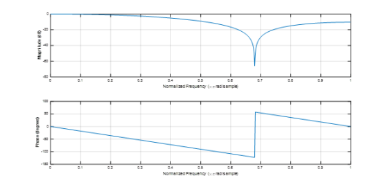
So the MATLAB script for obtaining the frequency response of the designed FIR filter
Case - I: When normalization is not required
clc;
clear all;
close all;
b = [1 1.0717 1];
a = 1;
freqz(b,a);
The frequency response in this case will be

Case II When we have normalized the filter
clc;
clear all;
close all;
b = [0.3256 0.3489 0.3256];
a = 1;
freqz(b,a);
The frequency response will be
Add Answer to:
In each of the problems please solve manually (which is worth 75% of the problem points)...
Topics: Filter Design by Pole Zero Placement PROBLEM Problem #2 . a) Design a simple FIR...
 Topics: Filter Design by Pole Zero Placement PROBLEM Problem #2 . a) Design a simple FIR second order filter with real coefficients, causal, stable and with unity AC gain. Its steady state response is required to be zero when the input is: xIn]cos [(T/3)n] u[n] H(z) R.O.C: answer: b) Find the frequency response for the previous filter. H(0) c) Sketch the magnitude frequency response. T/3 t/3 d) Find the filter impulse response. h[n] e) Verify that the steady state step...
Please Show All the Steps Carefully. Please include both Written and Matlab approach. Written meaning Approaching...
 Please Show All the Steps Carefully. Please include both Written
and Matlab approach. Written meaning Approaching the problem by
hand and not using Matlab at all. Highest rating will be given to
those who show all the Written and Mattab steps carefully. Do not
skip the Written Method at all! Show All Your Work, Please!
2. An FIR system is described by the following Difference equation y n)-0.5 (x(n) - x(n-2)) a. Find the frequency response of this filter and...
Please Show All the Steps Carefully. Please include both Written
and Matlab approach. Written meaning Approaching the problem by
hand and not using Matlab at all. Highest rating will be given to
those who show all the Written and Mattab steps carefully. Do not
skip the Written Method at all! Show All Your Work, Please!
2. An FIR system is described by the following Difference equation y n)-0.5 (x(n) - x(n-2)) a. Find the frequency response of this filter and...
Question2: (40 points]: Consider the system shown in the figure with the input signal xc(t) =...
 Question2: (40 points]: Consider the system shown in the figure with the input signal xc(t) = 3 cos(100t) + 2 cos(200t), sampling frequency ws = 600 rad/s, and final filter cutoff frequency w1 = 400 rad/s. The filter has an impulse response given byha[n] = 8[n – 1] + 8[n] + 8[n + 1]. a) [10 points] Find and plot the signal Xa(ein) b) [10 points] Find and plot the signals Ya(ejn) and yo (jw) c) [10 points] Find and...
Problem 5 (10 points): Circle "T" for True or "F" for False for each of the following statements ...
 Problem 5 (10 points): Circle "T" for True or "F" for False for each of the following statements T F For a smoothing filter given by y[n]-(1-a)x[n] + αy[n-1], where 0 < α 1, the effects of an individual input sample never die out. The following system, where N > 1, is a high-pass filter: TF N-1 T F If the output of a digital filter depends on both current and past input values, it is called T F An...
Problem 31: (34 points) 1. (10 points) A pulse width modulated (PWM) signal fPwM(t) in Figure...
 Problem 31: (34 points) 1. (10 points) A pulse width modulated (PWM) signal fPwM(t) in Figure 2. The symbol D represents a duty cycle, a number between zero and one. Determine the compact trigonometric Fourier series coefficients (Co C,11 %) of the signal f(t). 2. (10 points) One use of PWM is to generate variable DC voltages. While the PWM signal is not DC, you should be able to see from your results in part 1 that it hss a...
Solve the problems as directed. Each problem worth 15 points. Use the data declaration on the...
 Solve the problems as directed. Each problem worth 15 points. Use the data declaration on the first page of this Review the SPIM program on the right. Then answer the following questions: What does the program do and how does it accomplish its goal? What is the last operation the program performs before halting? Write down the exact console output.. text main: la St1 str next Ib St0, (St1) beqz Sto, off sub Ssp, Ssp, 4 sw St0, (Ssp) addi...
 Topics: Filter Design by Pole Zero Placement PROBLEM Problem #2 . a) Design a simple FIR second order filter with real coefficients, causal, stable and with unity AC gain. Its steady state response is required to be zero when the input is: xIn]cos [(T/3)n] u[n] H(z) R.O.C: answer: b) Find the frequency response for the previous filter. H(0) c) Sketch the magnitude frequency response. T/3 t/3 d) Find the filter impulse response. h[n] e) Verify that the steady state step...
 Please Show All the Steps Carefully. Please include both Written
and Matlab approach. Written meaning Approaching the problem by
hand and not using Matlab at all. Highest rating will be given to
those who show all the Written and Mattab steps carefully. Do not
skip the Written Method at all! Show All Your Work, Please!
2. An FIR system is described by the following Difference equation y n)-0.5 (x(n) - x(n-2)) a. Find the frequency response of this filter and...
Please Show All the Steps Carefully. Please include both Written
and Matlab approach. Written meaning Approaching the problem by
hand and not using Matlab at all. Highest rating will be given to
those who show all the Written and Mattab steps carefully. Do not
skip the Written Method at all! Show All Your Work, Please!
2. An FIR system is described by the following Difference equation y n)-0.5 (x(n) - x(n-2)) a. Find the frequency response of this filter and...
 Question2: (40 points]: Consider the system shown in the figure with the input signal xc(t) = 3 cos(100t) + 2 cos(200t), sampling frequency ws = 600 rad/s, and final filter cutoff frequency w1 = 400 rad/s. The filter has an impulse response given byha[n] = 8[n – 1] + 8[n] + 8[n + 1]. a) [10 points] Find and plot the signal Xa(ein) b) [10 points] Find and plot the signals Ya(ejn) and yo (jw) c) [10 points] Find and...
 Problem 5 (10 points): Circle "T" for True or "F" for False for each of the following statements T F For a smoothing filter given by y[n]-(1-a)x[n] + αy[n-1], where 0 < α 1, the effects of an individual input sample never die out. The following system, where N > 1, is a high-pass filter: TF N-1 T F If the output of a digital filter depends on both current and past input values, it is called T F An...
 Problem 31: (34 points) 1. (10 points) A pulse width modulated (PWM) signal fPwM(t) in Figure 2. The symbol D represents a duty cycle, a number between zero and one. Determine the compact trigonometric Fourier series coefficients (Co C,11 %) of the signal f(t). 2. (10 points) One use of PWM is to generate variable DC voltages. While the PWM signal is not DC, you should be able to see from your results in part 1 that it hss a...
 Solve the problems as directed. Each problem worth 15 points. Use the data declaration on the first page of this Review the SPIM program on the right. Then answer the following questions: What does the program do and how does it accomplish its goal? What is the last operation the program performs before halting? Write down the exact console output.. text main: la St1 str next Ib St0, (St1) beqz Sto, off sub Ssp, Ssp, 4 sw St0, (Ssp) addi...
Most questions answered within 3 hours.
-
You purchase your daily coffee at the Chemist’s Coffeehouse and
have a choice of two cups:...
asked 2 hours ago -
Which of the following pairs of chemicals could be used to make
a buffer solution?
A.)...
asked 2 hours ago -
Problem 16-51 Sales
Activity Variance (LO 16-3)Odessa, Inc., reports the following
information concerning operations for the...
asked 2 hours ago -
Pictured on the right are thee point charges Q1 = 18.4 μC, Q2 =
-30.6 μC,...
asked 2 hours ago -
A graduate student is conducting research in psychology and
needs to obtain the IQ scores of...
asked 3 hours ago -
R2.84: There are 2 defective products in a production lot of 10.
An inspector randomly selected...
asked 4 hours ago -
Consider the following equilibrium system: COCl2(g) CO(g) +
Cl2(g) A 10.00 L evacuated flask is filled...
asked 5 hours ago -
1) What are the two distinct steps that one needs to perform
when developing a data...
asked 5 hours ago -
2) Write a C++ program that uses a class called “Degree” to
obtain the trigonometric
values...
asked 6 hours ago -
1. In eukaryotic cells the genomes of
&
asked 6 hours ago -
The standard enthalpy of propanol (C3H7OH) is -303.0 kJ/mol.
Compute both of the
gross and net...
asked 6 hours ago -
Why PWM using H-bridge for control motor speed is more power
effiecient than the linear amplifier...
asked 6 hours ago