
Homework Answers
Please find attcahed image for the solution

Please give positive review.
Thank you.
Add Answer to:
Part A For the circuit in the figure calculatoo, if g = 1.8 A. (Figure 1)...
Part A In the circuit in (Figure 1) the voltage and current expressions are v=48e-25 V,...
 Part A In the circuit in (Figure 1) the voltage and current expressions are v=48e-25 V, t>0; i= 20e - 25 mA, t> 0+. Find R. Express your answer to three significant figures and include the appropriate units. ? R= Value Units Submit Request Answer Part B Find C Express your answer to three significant figures and include the appropriate units. μΑ ? C = Value Units Figure < 1 of 1 > Submit Request Answer Part C Find 7...
Problem 4.7 Consider the circuit shown in (Figure 1). The source voltage v1 is 40 V....
 Problem 4.7 Consider the circuit shown in (Figure 1). The source voltage v1 is 40 V. Resistance R1, R2 and R3 are 5 ,120 and 15 , respectively. The source current I is 25 mA Part A Find the power developed by the current source I in the circuit. Express your answer to three significant figures and include the appropriate units. НА Value Units Рi 3 Request Answer Submit Part B Figure 1 of 1 Find the power developed by...
Review Constan Consider the circuit of the figure (Figure 1). Part A If the voltage across...
 Review Constan Consider the circuit of the figure (Figure 1). Part A If the voltage across the 30- k2 resistor is measured with a 50-kN2 voltmeter, what does the meter read? Express your answer to two significant figures and include the appropriate units. μΑ. ? V50 kn = Value Units Submit Request Answer Part B If the voltage across the 30-k2 resistor is measured with a 250-k voltmeter, what does the meter read? Express your answer to two significant figures...
In the circuit in (Figure 1) the voltage and current expressions are v=48e-25 V, t> 0...
 In the circuit in (Figure 1) the voltage and current expressions are v=48e-25 V, t> 0 i= 20e mA, tot Part A -250 Find R Express your answer to three significant figures and include the appropriate units. НА ? R= Value Units Submit Request Answer Part B Find C. Express your answer to three significant figures and include the appropriate units. НА Figure < 1 of 1 C= Value Units i Submit Request Answer + Part C V R Find...
Please answer all parts Consider the circuit shown in (Figure 1). Suppose that Ve = 50070°V...
 Please answer all parts
Consider the circuit shown in (Figure 1). Suppose that Ve = 50070°V (rms). Express your answer to three significant figures and include the appropriate units. View Available Hint(s) IT HA ? 21 = Value Units Submit Part D Find the average power dissipated in the line when the capacitive reactance is connected across the load. Express your answer to three significant figures and include the appropriate units. THA th ? P- Value Units Submit Request Answer...
Please answer all parts
Consider the circuit shown in (Figure 1). Suppose that Ve = 50070°V (rms). Express your answer to three significant figures and include the appropriate units. View Available Hint(s) IT HA ? 21 = Value Units Submit Part D Find the average power dissipated in the line when the capacitive reactance is connected across the load. Express your answer to three significant figures and include the appropriate units. THA th ? P- Value Units Submit Request Answer...
Part A The current and voltage at the terminals of the inductor in the circuit are...
 Part A The current and voltage at the terminals of the inductor in the circuit are i(t)=(3.4+3.8e-40t)A,t20; v(t)=-63e-40tV,t20+.(Figure 1) Specify the numerical value of V: - Express your answer to three significant figures and include the appropriate units. НА, ? V = Value Units Submit Request Answer Part B Specify the numerical value of R. Express your answer to three significant figures and include the appropriate units. HA ? R= Value Units Submit Request Answer Figure < 1 of 1...
Review Constants Part A Find the power developed by the current source in the circuit(Figure 1)if...
 Review Constants Part A Find the power developed by the current source in the circuit(Figure 1)if v = 38.0 V and i = 30 mA. Express your answer to two significant figures and include the appropriate units. P30mA = Value Units Submit Request Answer Figure < 1 of 1 > Part B Find the power developed by the voltage source. Express your answer to two significant figures and include the appropriate units. 8022 w + 2023 CHA MO O ?...
The current and voltage at the terminals of the inductor in the circuit are i(t) =...
 The current and voltage at the terminals of the inductor in the circuit are i(t) = (4.2 +5e 401) A, t > 0; v (t) = -73e_404 V, t > 0+ (Figure 1) Part A Specify the numerical value of Vs Express your answer to three significant figures and include the appropriate units. HA ? Vs = Value Units Submit Request Answer Part B Specify the numerical value of Express your answer to three significant figures and include the appropriate...
\ Problem 6 Consider the circuit shown in (Figure 1). Suppose that V, = 480_0°V (rms)....
 \
Problem 6 Consider the circuit shown in (Figure 1). Suppose that V, = 480_0°V (rms). Part A Find the average power dissipated in the line in the figure Express your answer three significant figures and include the appropriate units. HHA ? P = Value Units Submit Request Answer Part B Figure 1 of 1 > Find the capacitive reactance that, when connected in parallel, with the load will make the load look purely resistive. Express your answer three significant...
\
Problem 6 Consider the circuit shown in (Figure 1). Suppose that V, = 480_0°V (rms). Part A Find the average power dissipated in the line in the figure Express your answer three significant figures and include the appropriate units. HHA ? P = Value Units Submit Request Answer Part B Figure 1 of 1 > Find the capacitive reactance that, when connected in parallel, with the load will make the load look purely resistive. Express your answer three significant...
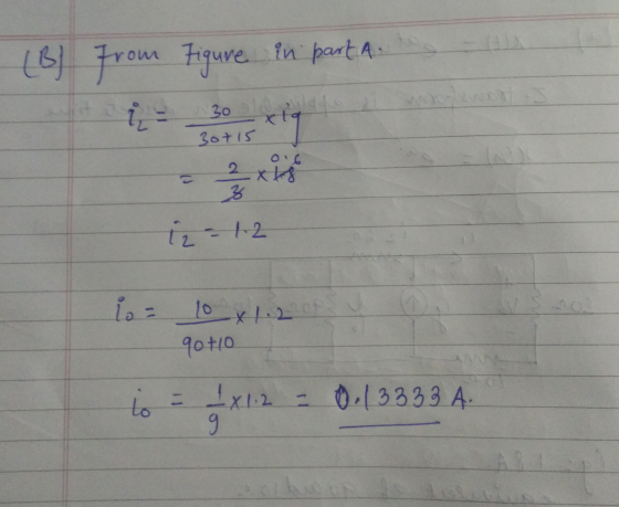
reviewIwona Consider the circuit in (Figure 1). Suppose that i = 1.6 A and y =...
 reviewIwona Consider the circuit in (Figure 1). Suppose that i = 1.6 A and y = 28 V Part A Use a series of source transformations to find in in the circuit. Express your answer to three significant figures and include the appropriate units. View Available Hint(s) μΑ ? 0.399 A Submit Previous Answers X Incorrect: Try Again: 4 attempts remaining Part B Complete previous part(s) Provide Feedback Next > Figure 1 of 1 > 612 02 5 Ω w...
 Part A In the circuit in (Figure 1) the voltage and current expressions are v=48e-25 V, t>0; i= 20e - 25 mA, t> 0+. Find R. Express your answer to three significant figures and include the appropriate units. ? R= Value Units Submit Request Answer Part B Find C Express your answer to three significant figures and include the appropriate units. μΑ ? C = Value Units Figure < 1 of 1 > Submit Request Answer Part C Find 7...
 Problem 4.7 Consider the circuit shown in (Figure 1). The source voltage v1 is 40 V. Resistance R1, R2 and R3 are 5 ,120 and 15 , respectively. The source current I is 25 mA Part A Find the power developed by the current source I in the circuit. Express your answer to three significant figures and include the appropriate units. НА Value Units Рi 3 Request Answer Submit Part B Figure 1 of 1 Find the power developed by...
 Review Constan Consider the circuit of the figure (Figure 1). Part A If the voltage across the 30- k2 resistor is measured with a 50-kN2 voltmeter, what does the meter read? Express your answer to two significant figures and include the appropriate units. μΑ. ? V50 kn = Value Units Submit Request Answer Part B If the voltage across the 30-k2 resistor is measured with a 250-k voltmeter, what does the meter read? Express your answer to two significant figures...
 In the circuit in (Figure 1) the voltage and current expressions are v=48e-25 V, t> 0 i= 20e mA, tot Part A -250 Find R Express your answer to three significant figures and include the appropriate units. НА ? R= Value Units Submit Request Answer Part B Find C. Express your answer to three significant figures and include the appropriate units. НА Figure < 1 of 1 C= Value Units i Submit Request Answer + Part C V R Find...
 Please answer all parts
Consider the circuit shown in (Figure 1). Suppose that Ve = 50070°V (rms). Express your answer to three significant figures and include the appropriate units. View Available Hint(s) IT HA ? 21 = Value Units Submit Part D Find the average power dissipated in the line when the capacitive reactance is connected across the load. Express your answer to three significant figures and include the appropriate units. THA th ? P- Value Units Submit Request Answer...
Please answer all parts
Consider the circuit shown in (Figure 1). Suppose that Ve = 50070°V (rms). Express your answer to three significant figures and include the appropriate units. View Available Hint(s) IT HA ? 21 = Value Units Submit Part D Find the average power dissipated in the line when the capacitive reactance is connected across the load. Express your answer to three significant figures and include the appropriate units. THA th ? P- Value Units Submit Request Answer...
 Part A The current and voltage at the terminals of the inductor in the circuit are i(t)=(3.4+3.8e-40t)A,t20; v(t)=-63e-40tV,t20+.(Figure 1) Specify the numerical value of V: - Express your answer to three significant figures and include the appropriate units. НА, ? V = Value Units Submit Request Answer Part B Specify the numerical value of R. Express your answer to three significant figures and include the appropriate units. HA ? R= Value Units Submit Request Answer Figure < 1 of 1...
 Review Constants Part A Find the power developed by the current source in the circuit(Figure 1)if v = 38.0 V and i = 30 mA. Express your answer to two significant figures and include the appropriate units. P30mA = Value Units Submit Request Answer Figure < 1 of 1 > Part B Find the power developed by the voltage source. Express your answer to two significant figures and include the appropriate units. 8022 w + 2023 CHA MO O ?...
 The current and voltage at the terminals of the inductor in the circuit are i(t) = (4.2 +5e 401) A, t > 0; v (t) = -73e_404 V, t > 0+ (Figure 1) Part A Specify the numerical value of Vs Express your answer to three significant figures and include the appropriate units. HA ? Vs = Value Units Submit Request Answer Part B Specify the numerical value of Express your answer to three significant figures and include the appropriate...
 \
Problem 6 Consider the circuit shown in (Figure 1). Suppose that V, = 480_0°V (rms). Part A Find the average power dissipated in the line in the figure Express your answer three significant figures and include the appropriate units. HHA ? P = Value Units Submit Request Answer Part B Figure 1 of 1 > Find the capacitive reactance that, when connected in parallel, with the load will make the load look purely resistive. Express your answer three significant...
\
Problem 6 Consider the circuit shown in (Figure 1). Suppose that V, = 480_0°V (rms). Part A Find the average power dissipated in the line in the figure Express your answer three significant figures and include the appropriate units. HHA ? P = Value Units Submit Request Answer Part B Figure 1 of 1 > Find the capacitive reactance that, when connected in parallel, with the load will make the load look purely resistive. Express your answer three significant...
 reviewIwona Consider the circuit in (Figure 1). Suppose that i = 1.6 A and y = 28 V Part A Use a series of source transformations to find in in the circuit. Express your answer to three significant figures and include the appropriate units. View Available Hint(s) μΑ ? 0.399 A Submit Previous Answers X Incorrect: Try Again: 4 attempts remaining Part B Complete previous part(s) Provide Feedback Next > Figure 1 of 1 > 612 02 5 Ω w...
Most questions answered within 3 hours.
-
Kenny Electric Company's noncallable bonds were issued several
years ago and now have 20 years to...
asked 54 seconds from now -
find H(e^Jtheta) at theta= 0, pi/10, pi/20, pi/2 for
the following:
a) H(e^Jtheta)= 1+e^Jtheta
b) H(e^Jtheta)=...
asked 28 minutes ago -
Home Corporation will open a new store on January 1. Based on
experience from its other...
asked 44 minutes ago -
In a neoclassical model, use the IS-LM to analyze the effect of
a permanent money supply...
asked 1 hour ago -
An electron passes through a point 2.67 cm from a long straight
wire as it moves...
asked 1 hour ago -
A grammar is a 4-tuple G, G = (Ν, Σ, Π, Σ, S) where, Ν is...
asked 2 hours ago -
In this part, calculate the present values. Use the Excel PV
function to compute the present...
asked 2 hours ago -
Part 1. Primitive Types, Sorting, Recursion for
Homework.java
a) Implement the static method initializeArray that receives...
asked 3 hours ago -
Using C++, build a sorter that can rank a sequence of numbers in
a descending order....
asked 3 hours ago -
Derive ground state term symbols. Use notation 2S(1/2) for state
2S1/2
a) d5
b) f3
c)...
asked 4 hours ago -
A sample of size 31 will be drawn from a population with mean 39
and standard...
asked 4 hours ago -
What is the effect on the P-value when a test is changed from a
two-tailed hypothesis...
asked 4 hours ago