 3. Digital circuits question.
Homework Answers


Add Answer to:
3. Digital circuits question.
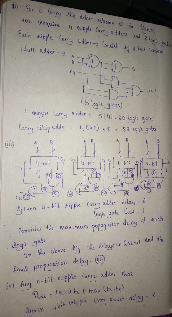
The figure below shows a 16-b carry-skip adder. It is composed of...
The composition of a Ripple Carry adder can be broken down into the basic logic gates...
The composition of a Ripple Carry adder can be broken down into the basic logic gates (and, or, and not gates) Ripple carry adder is made of multiple Full Adders. Each Full Adder requires an OR gate with two Half Adders Each Half Adder requires an AND gate and an XOR gate. Each XOR gate requires two NOT gates, two AND gates, and an OR gate. How man gates total are required to make a half adder? How many gates...
Consider a N-bit carry-skip adder with B bits per block. Assume that one stage of carry ripple (t...
Consider a N-bit carry-skip adder with B bits per block. Assume that one stage of carry ripple (tcarry) has the same delay of one skip logic stage (tskip) and both are 1. Determine the block size Bopt that mininizes the worse-case delay time Please provide a neat solution
3.Consider a N-bit carry-skip adder with B bits per block. Assume that one stage of carry rippler...
 ***Please be coherent and conscience.
3.Consider a N-bit carry-skip adder with B bits per block. Assume that one stage of carry ripplery) has the same delay of one skip logic stage (tskip) and both are 1. Determine the block size Bopt that mininizes the worse-case delay time.
3.Consider a N-bit carry-skip adder with B bits per block. Assume that one stage of carry ripplery) has the same delay of one skip logic stage (tskip) and both are 1. Determine the...
***Please be coherent and conscience.
3.Consider a N-bit carry-skip adder with B bits per block. Assume that one stage of carry ripplery) has the same delay of one skip logic stage (tskip) and both are 1. Determine the block size Bopt that mininizes the worse-case delay time.
3.Consider a N-bit carry-skip adder with B bits per block. Assume that one stage of carry ripplery) has the same delay of one skip logic stage (tskip) and both are 1. Determine the...
In the lookahead carry examples in the text, the span of the lookahead logic was 4 bits. Now assu...
 In the lookahead carry examples in the text, the span of the
lookahead logic was 4 bits. Now assume that the span of the
lookahead logic increases to 6 bits. Show the block diagram for a
32-bit adder similar to figure 9.5 in the text and compute what the
total gate delay is to c32 and s31 .
7-4 7-4 13-0 3-0 15-12 15-12 11-8 y11-8 C12 C8 C0 4-bit adder 4-bit adder 4-bit adder 4-bit adder C16 S11-8 S7-4...
In the lookahead carry examples in the text, the span of the
lookahead logic was 4 bits. Now assume that the span of the
lookahead logic increases to 6 bits. Show the block diagram for a
32-bit adder similar to figure 9.5 in the text and compute what the
total gate delay is to c32 and s31 .
7-4 7-4 13-0 3-0 15-12 15-12 11-8 y11-8 C12 C8 C0 4-bit adder 4-bit adder 4-bit adder 4-bit adder C16 S11-8 S7-4...
8/8pts Question 1 Using block diagram of 1-bit full adders create a 3-bit parallel adder (show...
 8/8pts Question 1 Using block diagram of 1-bit full adders create a 3-bit parallel adder (show all the connections between the adders and proper outputs Logic Q1jpg 4/9 pts Question 2 Consider your design, if the inputs to be added were 100, and 111, what will be the resulting sum output (Express the resulting sum in binary and base 8 using the least number of bits)? What will be the carry output (Express it only in binary using the least...
number 4 and 5 please! PROBLEM STATEMENT A logic circuit is needed to add multi-bit binary...
 number 4 and 5 please!
PROBLEM STATEMENT A logic circuit is needed to add multi-bit binary numbers. A 2-level circuit that would add two four-bit numbers would have 9 inputs and five outputs. Although a 2-level SOP or POS circuit theoretically would be very fast, it has numerous drawbacks that make it impractical. The design would be very complex in terms of the number of logic gates. The number of inputs for each gate would challenge target technologies. Testing would...
number 4 and 5 please!
PROBLEM STATEMENT A logic circuit is needed to add multi-bit binary numbers. A 2-level circuit that would add two four-bit numbers would have 9 inputs and five outputs. Although a 2-level SOP or POS circuit theoretically would be very fast, it has numerous drawbacks that make it impractical. The design would be very complex in terms of the number of logic gates. The number of inputs for each gate would challenge target technologies. Testing would...
 ***Please be coherent and conscience.
3.Consider a N-bit carry-skip adder with B bits per block. Assume that one stage of carry ripplery) has the same delay of one skip logic stage (tskip) and both are 1. Determine the block size Bopt that mininizes the worse-case delay time.
3.Consider a N-bit carry-skip adder with B bits per block. Assume that one stage of carry ripplery) has the same delay of one skip logic stage (tskip) and both are 1. Determine the...
***Please be coherent and conscience.
3.Consider a N-bit carry-skip adder with B bits per block. Assume that one stage of carry ripplery) has the same delay of one skip logic stage (tskip) and both are 1. Determine the block size Bopt that mininizes the worse-case delay time.
3.Consider a N-bit carry-skip adder with B bits per block. Assume that one stage of carry ripplery) has the same delay of one skip logic stage (tskip) and both are 1. Determine the...
 In the lookahead carry examples in the text, the span of the
lookahead logic was 4 bits. Now assume that the span of the
lookahead logic increases to 6 bits. Show the block diagram for a
32-bit adder similar to figure 9.5 in the text and compute what the
total gate delay is to c32 and s31 .
7-4 7-4 13-0 3-0 15-12 15-12 11-8 y11-8 C12 C8 C0 4-bit adder 4-bit adder 4-bit adder 4-bit adder C16 S11-8 S7-4...
In the lookahead carry examples in the text, the span of the
lookahead logic was 4 bits. Now assume that the span of the
lookahead logic increases to 6 bits. Show the block diagram for a
32-bit adder similar to figure 9.5 in the text and compute what the
total gate delay is to c32 and s31 .
7-4 7-4 13-0 3-0 15-12 15-12 11-8 y11-8 C12 C8 C0 4-bit adder 4-bit adder 4-bit adder 4-bit adder C16 S11-8 S7-4...
 8/8pts Question 1 Using block diagram of 1-bit full adders create a 3-bit parallel adder (show all the connections between the adders and proper outputs Logic Q1jpg 4/9 pts Question 2 Consider your design, if the inputs to be added were 100, and 111, what will be the resulting sum output (Express the resulting sum in binary and base 8 using the least number of bits)? What will be the carry output (Express it only in binary using the least...
 number 4 and 5 please!
PROBLEM STATEMENT A logic circuit is needed to add multi-bit binary numbers. A 2-level circuit that would add two four-bit numbers would have 9 inputs and five outputs. Although a 2-level SOP or POS circuit theoretically would be very fast, it has numerous drawbacks that make it impractical. The design would be very complex in terms of the number of logic gates. The number of inputs for each gate would challenge target technologies. Testing would...
number 4 and 5 please!
PROBLEM STATEMENT A logic circuit is needed to add multi-bit binary numbers. A 2-level circuit that would add two four-bit numbers would have 9 inputs and five outputs. Although a 2-level SOP or POS circuit theoretically would be very fast, it has numerous drawbacks that make it impractical. The design would be very complex in terms of the number of logic gates. The number of inputs for each gate would challenge target technologies. Testing would...
Most questions answered within 3 hours.
-
C++
Write a class Fraction that defines adding, subtracting,
multiplying, and dividing fractions by overloading standard...
asked 1 hour ago -
This java code won't run and I can't figure out the problem with
it. Please help...
asked 1 hour ago -
Trace the following recursive methods:
a) isPal with the string “abccda”
b) isAnBn with the string...
asked 2 hours ago -
1. Which of the following is false about photosynthesis?
A. ATP is the molecule used to...
asked 3 hours ago -
A simple random sample of size n=64 is obtained from a
population with a mean of...
asked 4 hours ago -
(2 dimensions, 1 object, 2 accelerations)
1) A projectile is thrown with a wind. The wind...
asked 5 hours ago -
Brian makes $34,100 per year. How much can Brian expect to
contribute to FICA taxes in...
asked 6 hours ago -
To buy a new house you must borrow $155,000. To do this you take
out a...
asked 6 hours ago -
Spacely Sprockets is evaluating the construction of a new plant
on land the company purchased for...
asked 7 hours ago -
1. Consider a linear regression model of y on K regressors and
an intercept.
(i) Describe...
asked 7 hours ago -
Enter a balanced equation for the reaction between hydrochloric
acid and sodium sulfite.
Express your answer...
asked 7 hours ago -
Give a regular expression describing the language
{x | x ∈ Σ* and x does not...
asked 7 hours ago