
Homework Answers
Add Answer to:
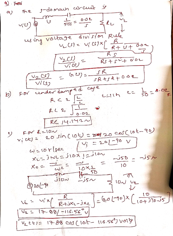
3) for the the ole termine the traw ausf voll the circuit be Let RE 10...
ke termine the er t For what Rwll the circuit be 1 Component of the v2...
 ke termine the er t For what Rwll the circuit be 1 Component of the v2 (t) respnsef th input signal is αχ(t) = 20 sin@st).
Problems: 1. Consider the system shown below. Let the input signal to the Ideal Sampler to be: s(...
 just looking for #2, 3, and 4
Problems: 1. Consider the system shown below. Let the input signal to the Ideal Sampler to be: s(t) = 2 cos(2m50t) + 4cos(2m100t) a. (10 points) Determine S(f) and plot it b. (20 points) Let the sampling rate to be: fs 300 samples/sec. Plot the spectrum of the Ideal sample, that is plot S8(f) c. Let the sampling rate to be: fs 175 samples/sec. i. (30 points) Plot S8(f) ii. (10 points) Let...
just looking for #2, 3, and 4
Problems: 1. Consider the system shown below. Let the input signal to the Ideal Sampler to be: s(t) = 2 cos(2m50t) + 4cos(2m100t) a. (10 points) Determine S(f) and plot it b. (20 points) Let the sampling rate to be: fs 300 samples/sec. Plot the spectrum of the Ideal sample, that is plot S8(f) c. Let the sampling rate to be: fs 175 samples/sec. i. (30 points) Plot S8(f) ii. (10 points) Let...
Problem 5) The approximate magnitude and phase values of a passive filter circuit is given in the...
 Problem 5) The approximate magnitude and phase values of a passive filter circuit is given in the Table P5 Table P5 Frequency Magnitude Phase 0 rad/s 50 500 4500 10000 dB -40 -20 -3 0 90 90 45 a) Find an expression for the output signal Vo(t) when input signal is vs(t)-10 sin(4500t+10) b) Find a steady-state expression for Vo(t) when input signal is vs(t)-50 cos(50t-45°).u(t) c) Find a steady-state expression for vo(t) when input signal is vs(t)-15 sin(10000t+550).u(t) d)...
ㆍ 3 (10) Let = Re', z = re (0<r< R) be two complex numbers. Show...
 ㆍ
3 (10) Let = Re', z = re (0<r< R) be two complex numbers. Show the following identities hold: R2 2 OO = Re = 1 +2 C-z ΣΑ. R2 - 2rR cos (-0)r2 coS n(-e) n=1
ㆍ
3 (10) Let = Re', z = re (0<r< R) be two complex numbers. Show the following identities hold: R2 2 OO = Re = 1 +2 C-z ΣΑ. R2 - 2rR cos (-0)r2 coS n(-e) n=1
5. [20 marks Consider the RC series circuit shown in Fig. 3. Determine the overall output...
 5. [20 marks Consider the RC series circuit shown in Fig. 3. Determine the overall output y(t). Determine the steady state output, yss(t), of the circuit if the input signal is given by r(t) = sin (3t) u(t) x(t) = sin(31) C = 0.5 μF Figure 3: RC series circuit for Q5
A21921 2. +9V Re Vout Re RE CE 0v Figure 3 (a) ) State the purpose of each of the capacitors Cin, Cout and Ce in the circuit [3 shown in Figure 3. (i) Derive an expression for the input resistanc...
 A21921 2. +9V Re Vout Re RE CE 0v Figure 3 (a) ) State the purpose of each of the capacitors Cin, Cout and Ce in the circuit [3 shown in Figure 3. (i) Derive an expression for the input resistance of this circuit in terms of the [5 mutual conductance of the transistor gm and its current gain β. we require an amplifier with a gain of-100, an output impedance of 1kΩ and an input impedance of 1k2. The...
Question 3 (1 point) Rsig vse {cB+1)re Bin La SRC SRL Vout The model for a...
 Question 3 (1 point) Rsig vse {cB+1)re Bin La SRC SRL Vout The model for a common-emitter small-signal BJT amplifier is shown. Determine the peak-to-peak value of Vout if Vsig = 100 mVpp- Assume B = 100, re = 20 s and ro = 50 k12. Other circuit values are Rsig = 1 ks, RC = 4k22 and RL = 10 k22 Ovout = 8.95 Vpp Ovout = 20.3 Vpp Ovout = 13.4 Vpp Ovout = 6.55 Vpp
Q6 A second CT system has the following pole-zero diagram: jw X S-plane Re х let...
 Q6
A second CT system has the following pole-zero diagram: jw X S-plane Re х let assume that the input signal is as follows {1; cos(t) > 0; otherwise. Let ak and by represent the Fourier series coefficients of the input and output signals, respectively, where the fundamental (lowest frequency component) of each signal has a period of 27. It is known that he . Determine , justify your answers mathematically.
Q6
A second CT system has the following pole-zero diagram: jw X S-plane Re х let assume that the input signal is as follows {1; cos(t) > 0; otherwise. Let ak and by represent the Fourier series coefficients of the input and output signals, respectively, where the fundamental (lowest frequency component) of each signal has a period of 27. It is known that he . Determine , justify your answers mathematically.
B A second CT system has the following pole-zero diagram: jw X S-plane Re х let...
 B
A second CT system has the following pole-zero diagram: jw X S-plane Re х let assume that the input signal is as follows {1; cos(t) > 0; otherwise. Let ak and by represent the Fourier series coefficients of the input and output signals, respectively, where the fundamental (lowest frequency component) of each signal has a period of 27. It is known that he . Determine , justify your answers mathematically.
B
A second CT system has the following pole-zero diagram: jw X S-plane Re х let assume that the input signal is as follows {1; cos(t) > 0; otherwise. Let ak and by represent the Fourier series coefficients of the input and output signals, respectively, where the fundamental (lowest frequency component) of each signal has a period of 27. It is known that he . Determine , justify your answers mathematically.
Problem 1 (Problem Solving Workshop 1) For a parallel RL circuit R-10, L 1H Determine 1)...
 Problem 1 (Problem Solving Workshop 1) For a parallel RL circuit R-10, L 1H Determine 1) 21 3) 4) The transfer function H(s) = (s), the pole-zero map, and the step response. Let L(0) - OA The state and output equations. Let Lt) be the state variable The block diagram of this system. Let (O) = -1 The response (t) due to a step input (t) = (t) A) using a known software. Problem #2 (Problem Solving Workshop 1) For...
 ke termine the er t For what Rwll the circuit be 1 Component of the v2 (t) respnsef th input signal is αχ(t) = 20 sin@st).
 just looking for #2, 3, and 4
Problems: 1. Consider the system shown below. Let the input signal to the Ideal Sampler to be: s(t) = 2 cos(2m50t) + 4cos(2m100t) a. (10 points) Determine S(f) and plot it b. (20 points) Let the sampling rate to be: fs 300 samples/sec. Plot the spectrum of the Ideal sample, that is plot S8(f) c. Let the sampling rate to be: fs 175 samples/sec. i. (30 points) Plot S8(f) ii. (10 points) Let...
just looking for #2, 3, and 4
Problems: 1. Consider the system shown below. Let the input signal to the Ideal Sampler to be: s(t) = 2 cos(2m50t) + 4cos(2m100t) a. (10 points) Determine S(f) and plot it b. (20 points) Let the sampling rate to be: fs 300 samples/sec. Plot the spectrum of the Ideal sample, that is plot S8(f) c. Let the sampling rate to be: fs 175 samples/sec. i. (30 points) Plot S8(f) ii. (10 points) Let...
 Problem 5) The approximate magnitude and phase values of a passive filter circuit is given in the Table P5 Table P5 Frequency Magnitude Phase 0 rad/s 50 500 4500 10000 dB -40 -20 -3 0 90 90 45 a) Find an expression for the output signal Vo(t) when input signal is vs(t)-10 sin(4500t+10) b) Find a steady-state expression for Vo(t) when input signal is vs(t)-50 cos(50t-45°).u(t) c) Find a steady-state expression for vo(t) when input signal is vs(t)-15 sin(10000t+550).u(t) d)...
 ㆍ
3 (10) Let = Re', z = re (0<r< R) be two complex numbers. Show the following identities hold: R2 2 OO = Re = 1 +2 C-z ΣΑ. R2 - 2rR cos (-0)r2 coS n(-e) n=1
ㆍ
3 (10) Let = Re', z = re (0<r< R) be two complex numbers. Show the following identities hold: R2 2 OO = Re = 1 +2 C-z ΣΑ. R2 - 2rR cos (-0)r2 coS n(-e) n=1
 5. [20 marks Consider the RC series circuit shown in Fig. 3. Determine the overall output y(t). Determine the steady state output, yss(t), of the circuit if the input signal is given by r(t) = sin (3t) u(t) x(t) = sin(31) C = 0.5 μF Figure 3: RC series circuit for Q5
 A21921 2. +9V Re Vout Re RE CE 0v Figure 3 (a) ) State the purpose of each of the capacitors Cin, Cout and Ce in the circuit [3 shown in Figure 3. (i) Derive an expression for the input resistance of this circuit in terms of the [5 mutual conductance of the transistor gm and its current gain β. we require an amplifier with a gain of-100, an output impedance of 1kΩ and an input impedance of 1k2. The...
 Question 3 (1 point) Rsig vse {cB+1)re Bin La SRC SRL Vout The model for a common-emitter small-signal BJT amplifier is shown. Determine the peak-to-peak value of Vout if Vsig = 100 mVpp- Assume B = 100, re = 20 s and ro = 50 k12. Other circuit values are Rsig = 1 ks, RC = 4k22 and RL = 10 k22 Ovout = 8.95 Vpp Ovout = 20.3 Vpp Ovout = 13.4 Vpp Ovout = 6.55 Vpp
 Q6
A second CT system has the following pole-zero diagram: jw X S-plane Re х let assume that the input signal is as follows {1; cos(t) > 0; otherwise. Let ak and by represent the Fourier series coefficients of the input and output signals, respectively, where the fundamental (lowest frequency component) of each signal has a period of 27. It is known that he . Determine , justify your answers mathematically.
Q6
A second CT system has the following pole-zero diagram: jw X S-plane Re х let assume that the input signal is as follows {1; cos(t) > 0; otherwise. Let ak and by represent the Fourier series coefficients of the input and output signals, respectively, where the fundamental (lowest frequency component) of each signal has a period of 27. It is known that he . Determine , justify your answers mathematically.
 B
A second CT system has the following pole-zero diagram: jw X S-plane Re х let assume that the input signal is as follows {1; cos(t) > 0; otherwise. Let ak and by represent the Fourier series coefficients of the input and output signals, respectively, where the fundamental (lowest frequency component) of each signal has a period of 27. It is known that he . Determine , justify your answers mathematically.
B
A second CT system has the following pole-zero diagram: jw X S-plane Re х let assume that the input signal is as follows {1; cos(t) > 0; otherwise. Let ak and by represent the Fourier series coefficients of the input and output signals, respectively, where the fundamental (lowest frequency component) of each signal has a period of 27. It is known that he . Determine , justify your answers mathematically.
 Problem 1 (Problem Solving Workshop 1) For a parallel RL circuit R-10, L 1H Determine 1) 21 3) 4) The transfer function H(s) = (s), the pole-zero map, and the step response. Let L(0) - OA The state and output equations. Let Lt) be the state variable The block diagram of this system. Let (O) = -1 The response (t) due to a step input (t) = (t) A) using a known software. Problem #2 (Problem Solving Workshop 1) For...
Most questions answered within 3 hours.
-
(CO 2) A field can be added to a report to
values for two or more...
asked 1 hour ago -
Identify 3 research scenarios that might provide a low,
medium, and high degree of variability in...
asked 2 hours ago -
how
does gravity affect the trajectory of projectile? what would be the
shape of the trajactory...
asked 2 hours ago -
Two small plastic spheres are given positive electrical charges.
When they are a distance of 15.4...
asked 3 hours ago -
An acidic solution containing gold ions is
electrolyzed, producing gaseous oxygen (from water) at the anode...
asked 3 hours ago -
Assume that the population of Mexico is 128
million and that the population increases 1.01
percentannually....
asked 4 hours ago -
Can someone please help me add appropriate descriptive
comments to each line of code in the...
asked 4 hours ago -
Romeo wishes to throw a bouquet of flowers to Juliet, who is on
a second-story balcony,...
asked 5 hours ago -
Why is QE a controversial monetary policy tool.
A. It may lead to excessive inflation.B. By...
asked 5 hours ago -
Principles of Programming midterm study guide help!
1.)
______ Which of the following would reference the...
asked 5 hours ago -
A finite potential well has depth U0 = 2.78 eV . What is the
penetration distance...
asked 6 hours ago -
1. The bus bars of a power station are in two sections A and B
separated...
asked 5 hours ago