

Homework Answers
Answer #1
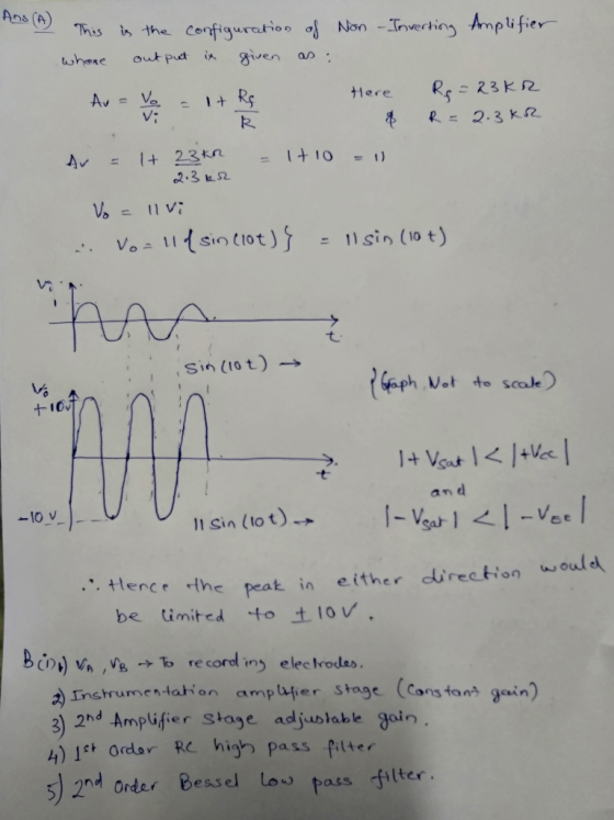


Ans () This is the Configuration ơ1 Non -Invertins Amplifie 23 k2 Sin(lot) → Sat 七 11 sin (tot) → he peat in either direation woul d be United-to±10v', ) Instrumentahion amplufer stage Cansfan gein) 3) 2nd Ampüfer staye adjuslabe goin 4) 1t ordar Re 52nd ndar Besel lo pass filter hih pass Pitter
24 shye amplifier. For tro, +ne ean. 4.2 -다ㅡㅡ Vo K.R om the sen ciot LPF. eciden the Cut oppesite rcbiter provided the HPF sHage ges e liminates. gt ys 1시 ed fo fu sh ㅢhe previouD$140a_人 betoreanalゲsing Nas signal
We were unable to transcribe this image
We were unable to transcribe this image
We were unable to transcribe this image
Know the answer?
Add Answer to:
Question 2: Conditioning CIPeuIL A. The circuit in Figure 1 is used to amplify the input...
Not the answer you're looking for?
Ask your own homework help question.
Our experts will answer your question WITHIN MINUTES for Free.
Similar Homework Help Questions
Question 1: 7.33 +15V 1O MO R-200k 16n 7k MO 7.33 Figure P7.33 shows a discrete-circuit...
 Question 1: 7.33 +15V 1O MO R-200k 16n 7k MO 7.33 Figure P7.33 shows a discrete-circuit amplifier. The input signal is coupled to the gate through a very large capacitor (shown as infinite). The transistor source is connected to ground at signal frequencies via a very large capacitor (shown as infinite). The output voltage signal that develops at the drain is coupled to a load resistance via a very large capacitor (shown as infinite). All capacitors behave as short circuits...
 Question 1: 7.33 +15V 1O MO R-200k 16n 7k MO 7.33 Figure P7.33 shows a discrete-circuit amplifier. The input signal is coupled to the gate through a very large capacitor (shown as infinite). The transistor source is connected to ground at signal frequencies via a very large capacitor (shown as infinite). The output voltage signal that develops at the drain is coupled to a load resistance via a very large capacitor (shown as infinite). All capacitors behave as short circuits...
ADVERTISEMENT
Need Online Homework Help?
Ask
a QuestionGet Answers For Free
Most questions answered within 3 hours.
Most questions answered within 3 hours.
ADVERTISEMENT
ADVERTISEMENT
Active Questions
-
What percent of revenue does net income represent for each
year?
Total Revenue
2017 = 60,319,000...
asked 9 minutes ago -
For Ti+2 (Z=22). Determine the correct ground state
& # of microstates. Use the correct tanabe...
asked 12 minutes ago -
Why did so many investment banks have to start buying CDO’s and
other mortgaged backed securities...
asked 27 minutes ago -
The mean cost of domestic airfares in the United States rose to
an all-time high of...
asked 38 minutes ago -
1.Magazine Luiza is a Brazilian retail chain for consumer
electronics. The company currently has 100 stores...
asked 37 minutes ago -
What is the molarity of ZnCl2 that forms when 25.0 g of zinc
completely reacts with...
asked 39 minutes ago -
For independent X and Y, we have probability density function
for them where pdf of X...
asked 49 minutes ago -
The decomposition of SO2Cl2 is first order in SO2Cl2 and has a
rate constant of 1.42...
asked 45 minutes ago -
How do I convert from volume percent to mole percent in the
distillation lab? ethy acetate...
asked 52 minutes ago -
8. An air-plane has an effective wing surface area of 14.0 m²
that is generating the...
asked 53 minutes ago -
A railroad worker was a person who worked on setting and moving
railroad tracks. In securing...
asked 52 minutes ago -
using RECURSIVE Functions in Java, create a public static String
doubleLetters (String word)
For ex) that...
asked 59 minutes ago
ADVERTISEMENT