
Homework Answers
Add Answer to:
Problem 5. Use phasor techniques to analyze the circuit shown below and answer the following questions....
You have the following circuit in sinusoidal steady-state. Use phasor circuit analysis to find the time...
 You have the following circuit in sinusoidal
steady-state.
Use phasor circuit analysis to find the time domain expression
for the steady-state current, i(t), and steady-state voltages,
VR(t), VC(t) and VL(t).
Vs(t) = 50 cos(1000t) Volts.
Problem 1 (20 points) You have the following circuit in sinusoidal steady-state. Use phasor circuit analysis to find the time domain expression for the steady-state current, i(t), and steady- state voltages, Vr(t), Vc(t) and Vl(t). Vs(t) = 50 cos(1000t) Volts. i(t) 100 12 25 mH...
You have the following circuit in sinusoidal
steady-state.
Use phasor circuit analysis to find the time domain expression
for the steady-state current, i(t), and steady-state voltages,
VR(t), VC(t) and VL(t).
Vs(t) = 50 cos(1000t) Volts.
Problem 1 (20 points) You have the following circuit in sinusoidal steady-state. Use phasor circuit analysis to find the time domain expression for the steady-state current, i(t), and steady- state voltages, Vr(t), Vc(t) and Vl(t). Vs(t) = 50 cos(1000t) Volts. i(t) 100 12 25 mH...
4.15. Use phasor techniques in the following. (a) Find 2 cos(100t - 459) – 3 cos...
 4.15. Use phasor techniques in the following. (a) Find 2 cos(100t - 459) – 3 cos (100t + 60°) (b) Find 50 sin(100t) + (d/dt) cos (100t - 30). Hint: Do not take the derivative in the time domain; replace it by jo in the frequency domain. (c) Use phasor techniques to evaluate the derivative the formula in the time domain and transform of i(t) = 20 sin(500t) at t = 2 ms. Hint: Write into the frequency domain, using...
6. (20) Transform the circuit below to phasor domain. Sketch and completely label the transformed circuit....
 6. (20) Transform the circuit below to phasor domain. Sketch and completely label the transformed circuit. Find the steady state value of i(t). (Hint: Find the current (I) in the phasor domain then convert it back to the time domain to find i(t).) 15 F 375mH 30 cos (377t-15°) V
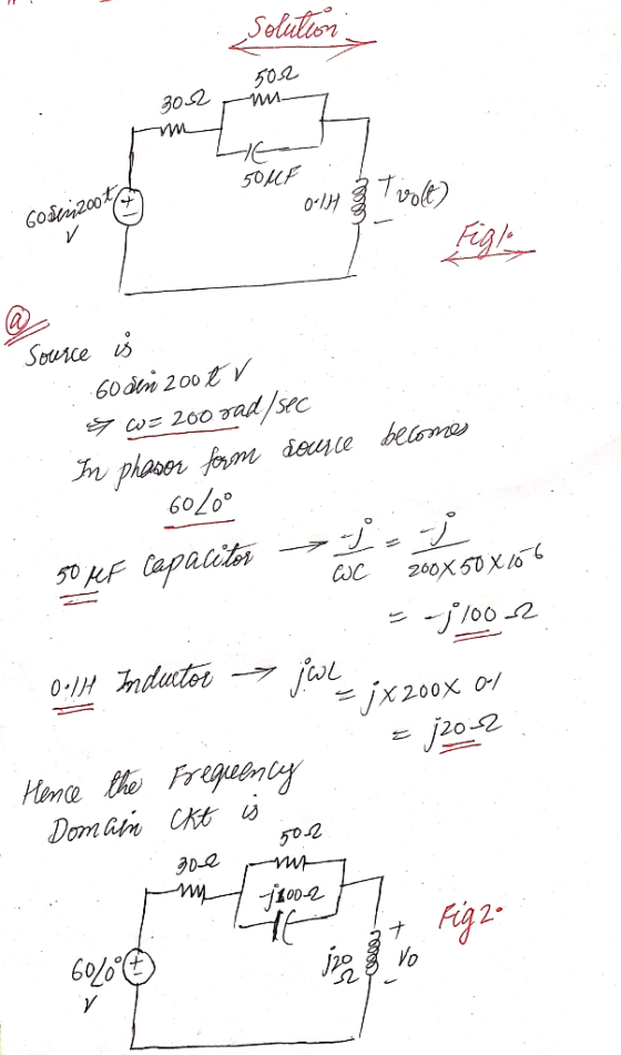
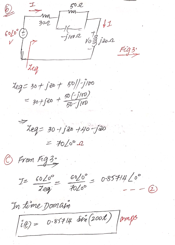
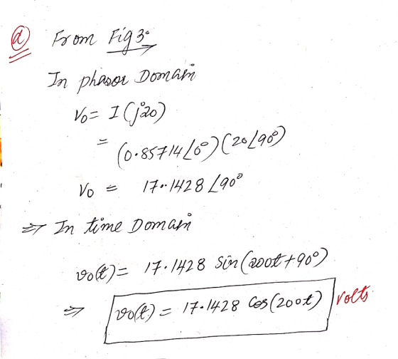
For the circuit shown below. Ifv.(t) = 100 cos(2001+30) V and vy(t) = 50 cos(2000) V....
 For the circuit shown below. Ifv.(t) = 100 cos(2001+30) V and vy(t) = 50 cos(2000) V. a) Redraw the circuit using Phasor equivalent. b) In the Phasor domain, find the node voltage equations. 1 mF 20 ml 30 000 30 mH 0.25 mF
2502 In the adjoining circuit schematic, in steady-state, the current flowing through the loop causes a...
 2502 In the adjoining circuit schematic, in steady-state, the current flowing through the loop causes a voltage drop across the resistor, having the waveform vr(t) = 15 cos (75 t) and a voltage drop across the capacitor given by ve(t) = 20 cos (75 t +90°) (a) Express the above two voltages in phasor form. (b) Find the source voltage shown in the circuit schematic, expressed in phasor form. (c) Express the source voltage v(t) as a function of time....
Problem #7) Perform a steady-state AC phasor analysis of the circuit shown below in order to...
 Problem #7) Perform a steady-state AC phasor analysis of the circuit shown below in order to determine the RMS phasor values of the source current I, and the resistor voltage V, as shown in the figure, along with the value of the reactive power Qs produced by the voltage source: He v(t)=2.277-sin(0-t) 0=27. f ſ 60F f = 60 Hz vo 210 mH3 son Qs - - VARS
please fully explain all parts Question 1: Answer all eight parts of Question 1. All questions...
 please fully explain all parts
Question 1: Answer all eight parts of Question 1. All questions carry an equal 5 marks. (i) What is the output voltage of the circuit shown in Figure 1.1? Assume ideal op- amp behaviour. 24 22 min m 10v lov o su Figure 1.1 (ii) Find the current in the 3 resistor in Figure 1.2. 20v – 30 20 Figure 1.2 - + ~ Fit to page Page view (ii) What is the current flowing...
please fully explain all parts
Question 1: Answer all eight parts of Question 1. All questions carry an equal 5 marks. (i) What is the output voltage of the circuit shown in Figure 1.1? Assume ideal op- amp behaviour. 24 22 min m 10v lov o su Figure 1.1 (ii) Find the current in the 3 resistor in Figure 1.2. 20v – 30 20 Figure 1.2 - + ~ Fit to page Page view (ii) What is the current flowing...
250 22 Problem 3. (9 Points) In the adjoining circuit schematic, in steady-state, the current flowing...
 250 22 Problem 3. (9 Points) In the adjoining circuit schematic, in steady-state, the current flowing through the loop causes a voltage drop across the resistor, having the waveform vr(t) = 15 cos (75 t) and a voltage drop across the capacitor given by ve(t) = 20 cos (75 t +90) (a) Express the above two voltages in phasor form. (b) Find the source voltage shown in the circuit schematic, expressed in phasor form. (c) Express the source voltage v(t)...
Problem 1: For the circuit below, use TIME DOMAIN TECHNIQUES. a) Find v, i, and the...
 Problem 1: For the circuit below, use TIME DOMAIN TECHNIQUES. a) Find v, i, and the time constant. Clearly show your work in the document that you submit after the test. b) Enter the time constant, v(O), and i(0) into Blackboard. c) Sketch the time response of this circuit. Remember to label your axis!!! 312 10u(-t) V (+) 0.1 F + WWW (4) lut)A
estion 130 Paint Consider the circuit below and answer the following questions: 1022 492 0.01 F...
 estion 130 Paint Consider the circuit below and answer the following questions: 1022 492 0.01 F ix 592 w 10 cos(101 - 10°) V WW 322 1Η Q2. a. 10 Points Draw the phasor domain circuit. Q2. b. [10 Points) Calculate the total impedance seen by the voltage source. Show your detailed solution.
 You have the following circuit in sinusoidal
steady-state.
Use phasor circuit analysis to find the time domain expression
for the steady-state current, i(t), and steady-state voltages,
VR(t), VC(t) and VL(t).
Vs(t) = 50 cos(1000t) Volts.
Problem 1 (20 points) You have the following circuit in sinusoidal steady-state. Use phasor circuit analysis to find the time domain expression for the steady-state current, i(t), and steady- state voltages, Vr(t), Vc(t) and Vl(t). Vs(t) = 50 cos(1000t) Volts. i(t) 100 12 25 mH...
You have the following circuit in sinusoidal
steady-state.
Use phasor circuit analysis to find the time domain expression
for the steady-state current, i(t), and steady-state voltages,
VR(t), VC(t) and VL(t).
Vs(t) = 50 cos(1000t) Volts.
Problem 1 (20 points) You have the following circuit in sinusoidal steady-state. Use phasor circuit analysis to find the time domain expression for the steady-state current, i(t), and steady- state voltages, Vr(t), Vc(t) and Vl(t). Vs(t) = 50 cos(1000t) Volts. i(t) 100 12 25 mH...
 4.15. Use phasor techniques in the following. (a) Find 2 cos(100t - 459) – 3 cos (100t + 60°) (b) Find 50 sin(100t) + (d/dt) cos (100t - 30). Hint: Do not take the derivative in the time domain; replace it by jo in the frequency domain. (c) Use phasor techniques to evaluate the derivative the formula in the time domain and transform of i(t) = 20 sin(500t) at t = 2 ms. Hint: Write into the frequency domain, using...
 6. (20) Transform the circuit below to phasor domain. Sketch and completely label the transformed circuit. Find the steady state value of i(t). (Hint: Find the current (I) in the phasor domain then convert it back to the time domain to find i(t).) 15 F 375mH 30 cos (377t-15°) V
 For the circuit shown below. Ifv.(t) = 100 cos(2001+30) V and vy(t) = 50 cos(2000) V. a) Redraw the circuit using Phasor equivalent. b) In the Phasor domain, find the node voltage equations. 1 mF 20 ml 30 000 30 mH 0.25 mF
 2502 In the adjoining circuit schematic, in steady-state, the current flowing through the loop causes a voltage drop across the resistor, having the waveform vr(t) = 15 cos (75 t) and a voltage drop across the capacitor given by ve(t) = 20 cos (75 t +90°) (a) Express the above two voltages in phasor form. (b) Find the source voltage shown in the circuit schematic, expressed in phasor form. (c) Express the source voltage v(t) as a function of time....
 Problem #7) Perform a steady-state AC phasor analysis of the circuit shown below in order to determine the RMS phasor values of the source current I, and the resistor voltage V, as shown in the figure, along with the value of the reactive power Qs produced by the voltage source: He v(t)=2.277-sin(0-t) 0=27. f ſ 60F f = 60 Hz vo 210 mH3 son Qs - - VARS
 please fully explain all parts
Question 1: Answer all eight parts of Question 1. All questions carry an equal 5 marks. (i) What is the output voltage of the circuit shown in Figure 1.1? Assume ideal op- amp behaviour. 24 22 min m 10v lov o su Figure 1.1 (ii) Find the current in the 3 resistor in Figure 1.2. 20v – 30 20 Figure 1.2 - + ~ Fit to page Page view (ii) What is the current flowing...
please fully explain all parts
Question 1: Answer all eight parts of Question 1. All questions carry an equal 5 marks. (i) What is the output voltage of the circuit shown in Figure 1.1? Assume ideal op- amp behaviour. 24 22 min m 10v lov o su Figure 1.1 (ii) Find the current in the 3 resistor in Figure 1.2. 20v – 30 20 Figure 1.2 - + ~ Fit to page Page view (ii) What is the current flowing...
 250 22 Problem 3. (9 Points) In the adjoining circuit schematic, in steady-state, the current flowing through the loop causes a voltage drop across the resistor, having the waveform vr(t) = 15 cos (75 t) and a voltage drop across the capacitor given by ve(t) = 20 cos (75 t +90) (a) Express the above two voltages in phasor form. (b) Find the source voltage shown in the circuit schematic, expressed in phasor form. (c) Express the source voltage v(t)...
 Problem 1: For the circuit below, use TIME DOMAIN TECHNIQUES. a) Find v, i, and the time constant. Clearly show your work in the document that you submit after the test. b) Enter the time constant, v(O), and i(0) into Blackboard. c) Sketch the time response of this circuit. Remember to label your axis!!! 312 10u(-t) V (+) 0.1 F + WWW (4) lut)A
 estion 130 Paint Consider the circuit below and answer the following questions: 1022 492 0.01 F ix 592 w 10 cos(101 - 10°) V WW 322 1Η Q2. a. 10 Points Draw the phasor domain circuit. Q2. b. [10 Points) Calculate the total impedance seen by the voltage source. Show your detailed solution.
Most questions answered within 3 hours.
-
How do I write a C program called binary that takes a single
command line argument,...
asked 6 minutes ago -
if total energy due two
electron is 1ev the distance between them is ?
asked 3 minutes ago -
Please help!!
Histidine is a polyprotic acid.
1. Draw a complete titration curve assuming 10.0 mL...
asked 6 minutes ago -
assume the salaries of elementary school teachers in the United
States normally distributed with a mean...
asked 9 minutes ago -
Question 10 - According to the Chapter Perspective, anti-hugging
policies have done which of the following?...
asked 12 minutes ago -
Research and explain how a hobby servo motor uses the pulse
width of the control signal...
asked 16 minutes ago -
To construct a solenoid, you wrap insulated wire uniformly
around a plastic tube 14 cm in...
asked 30 minutes ago -
Using traditional methods it takes 11.4 hours to receive a basic
driving license. A new license...
asked 35 minutes ago -
From the Principle of Conservation of Linear Moment, obtain the
Cauchy Movement equations in the Eulerian...
asked 47 minutes ago -
A
solution is made by disolving 2.54 mg of sodium benzoate in 75.00
kg H20
a)...
asked 53 minutes ago -
Sketch the crystal field splitting diagram for the low-spin
[Fe(CN)6 ] 4 - ion.
asked 55 minutes ago -
Sketch the homonuclear diatomic MO diagram for
Mo22+. What kind of magnetism does this dimer
exhibit?
asked 1 hour ago