Figure Q1(b) shows a beam AD which is loaded with the force F.
The coefficient of static friction at the top and bottom surfaces
of the wedge are ???=0.25 and ???=0.35, respectively. Neglect the
weight, size of the wedge and the thickness of the beam.
Considering the value of F from the Table Q1(b) attached, answer
the following;
(i) Draw the free body diagram of the given problem with all forces
and support reactions.
(2 marks)
(ii) Determine the horizontal force P which must be applied to the
wedge in order to remove it from under the beam.
(iii) If P=0, will there be self-locking of wedge?
F= 3000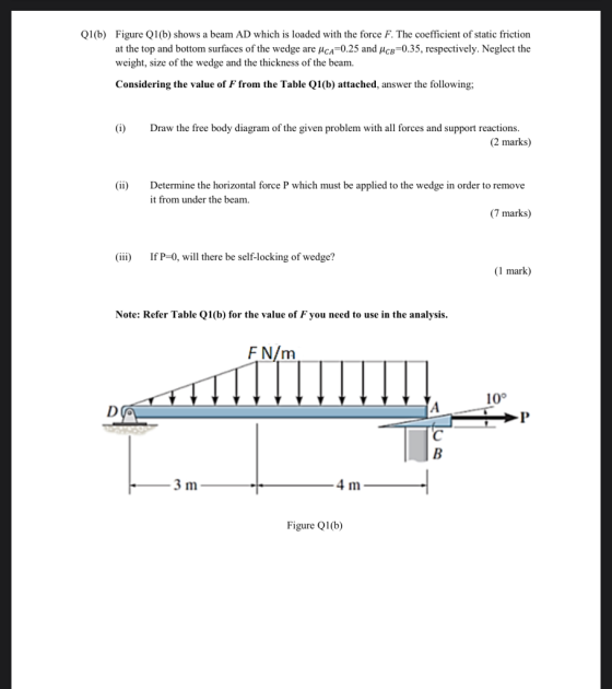
Homework Answers

Add Answer to:
Figure Q1(b) shows a beam AD which is loaded with the force F.
The coefficient of...
Problem 3 C 3 of 3 (Figure 1) If the beam AD is loaded as shown, determine the hornzontal force P...
 Problem 3 C 3 of 3 (Figure 1) If the beam AD is loaded as shown, determine the hornzontal force P whch must be applied to the rom under the beam The coefficents of static fnction at the wodge's top and botiom surtaces ane ca-035 and pee 0 40, respectively Neglect the weight and size of the wedge and the thickness of the beam Express your answer to three significant figures and include the appropriate units Figure 1 of 1...
REVIEW (Figure 1) Part A Determine the minimum applied force P required to move wedge A...
 REVIEW (Figure 1) Part A Determine the minimum applied force P required to move wedge A to the right. The spring is compressed a distance of 180 mm. Neglect the weight of A and B. The coefficient of static friction for all contacting surfaces is His = 0.35. Neglect friction at the rollers. Express your answer to three significant figures and include the appropriate units. Figure ? НА 1 of 1 P= Value Units k - 15 kN/m Submit Request...
If the applied force P = 250 N, determine (a) the required minimum compression in the...
 If the applied force P = 250 N, determine (a) the required
minimum compression in the spring so that the wedge will not move
to the right. Neglect the weight of A and B. The coefficient of
static friction for all contacting surfaces (i.e. between B &
A, and A & C) is ? = 0.35. Neglect friction at the rollers.
(b) Draw the free body diagram of object A. (Final Answer =
0.0183 m)
If the applied force P = 250 N, determine (a) the required
minimum compression in the spring so that the wedge will not move
to the right. Neglect the weight of A and B. The coefficient of
static friction for all contacting surfaces (i.e. between B &
A, and A & C) is ? = 0.35. Neglect friction at the rollers.
(b) Draw the free body diagram of object A. (Final Answer =
0.0183 m)
A bent rod is supported by smooth journal bearings at A and B. Assume the rod...
 A bent rod is supported by smooth journal bearings at A and B. Assume the rod is properly aligned. Find the reactions at all the supports, where F 600N 100N 30 Determine the intenal force, shear, and the moments at points B and C of figure 2. 4kN/m 3m 45° 1m 2m 2m Rajah 2IFigure 2 The compound beam shown in Figure 3 is pin connected at B. Determine the components of reaction at its support. Neglect its weight and...
The coefficient of static friction between A and C and between B and D is μs = 0.25, and between A and B is μs = 0.41. Neglect the weight of each wedge. (Figure 1)
 The coefficient of static friction between A and C and between B and D is μs = 0.25, and between A and B is μs = 0.41. Neglect the weight of each wedge. (Figure 1)
The machine part ABC is supported by a frictionless hinge at B and a 20° wedge at C. Knowing that the static coefficient of friction at both surfaces of the wedge is 0.3. Determine: (a) the force...
 The machine part ABC is supported by a frictionless hinge at B and a 20° wedge at C. Knowing that the static coefficient of friction at both surfaces of the wedge is 0.3. Determine: (a) the force P required to move the wedge. (b) The components of the corresponding reaction at B (c). Draw the normal, shear and moment diagrams [40 pts 5. 1800N A 350mm 10000 N/m 400mm 600mm
The machine part ABC is supported by a frictionless hinge...
The machine part ABC is supported by a frictionless hinge at B and a 20° wedge at C. Knowing that the static coefficient of friction at both surfaces of the wedge is 0.3. Determine: (a) the force P required to move the wedge. (b) The components of the corresponding reaction at B (c). Draw the normal, shear and moment diagrams [40 pts 5. 1800N A 350mm 10000 N/m 400mm 600mm
The machine part ABC is supported by a frictionless hinge...
Figure 5 shows a crate has a mass of 50 kg and the coefficient of static...
 Figure 5 shows a crate has a mass of 50 kg and the coefficient of static friction between the crate and the plane is us = 0.25. (1) Determine the minimum horizontal force P required to hold the crate from sliding down the plane. (8 marks) Determine the minimum force P required to push the crate up the plane. (8 marks) (11) P 30° Figure Q5
Q2(c) Figure Q1(c) shows a simply supported beam ABCD loaded as shown. The beam is pin-supported...
 Q2(c) Figure Q1(c) shows a simply supported beam ABCD loaded as shown. The beam is pin-supported at D, while point B is roller-supported. Determine the support reactions. b) For span BC (2<x< 4) write down the x-dependent equation for moment. x should be measured from cnd A. Plot the shear force diagram and the bending moment diagram for the beam. Show all important values of the diagrams. d) Plot the deflected shape of the beam. c) 50KN 40kN/m 25kNm 20kN/m...
Beam with bending load The beam AD below is made of steel A-36 and has a cross section as indicated. This beam is loaded between A and B with a distributed load with intensity w and at D with a vertical force P downwards. At A the beam is supported with a
 Beam with bending loadThe beam AD below is made of steel A-36 and has a cross section as indicated. This beam is loaded between A and B with a distributed load with intensity w and at D with a vertical force P downwards. At A the beam is supported with a fixed clamping and at C with a roller bearing. The own weight of the beam may be neglected. Handle the orientation of the given x-y axis system. L=185Determine all support...
(9 points) Difficulty (3/5) A S20x75 I-beam is loaded and supported as shown, with F =...
 (9 points) Difficulty (3/5) A S20x75 I-beam is loaded and supported as shown, with F = 7.8 kip. The dirmensions on the figure are a = 5 6 ft and b 1.96 ft Accounting for the self weight of the beam, determine the reactions at the support and the maximum stress in the beam. Report upward forces and counter-clockwise moments as positive and downward forces and clock-wise moments as negative. Report your stress as a psoitive value Answers: Rpall Muall
 Problem 3 C 3 of 3 (Figure 1) If the beam AD is loaded as shown, determine the hornzontal force P whch must be applied to the rom under the beam The coefficents of static fnction at the wodge's top and botiom surtaces ane ca-035 and pee 0 40, respectively Neglect the weight and size of the wedge and the thickness of the beam Express your answer to three significant figures and include the appropriate units Figure 1 of 1...
 REVIEW (Figure 1) Part A Determine the minimum applied force P required to move wedge A to the right. The spring is compressed a distance of 180 mm. Neglect the weight of A and B. The coefficient of static friction for all contacting surfaces is His = 0.35. Neglect friction at the rollers. Express your answer to three significant figures and include the appropriate units. Figure ? НА 1 of 1 P= Value Units k - 15 kN/m Submit Request...
 If the applied force P = 250 N, determine (a) the required
minimum compression in the spring so that the wedge will not move
to the right. Neglect the weight of A and B. The coefficient of
static friction for all contacting surfaces (i.e. between B &
A, and A & C) is ? = 0.35. Neglect friction at the rollers.
(b) Draw the free body diagram of object A. (Final Answer =
0.0183 m)
If the applied force P = 250 N, determine (a) the required
minimum compression in the spring so that the wedge will not move
to the right. Neglect the weight of A and B. The coefficient of
static friction for all contacting surfaces (i.e. between B &
A, and A & C) is ? = 0.35. Neglect friction at the rollers.
(b) Draw the free body diagram of object A. (Final Answer =
0.0183 m)
 A bent rod is supported by smooth journal bearings at A and B. Assume the rod is properly aligned. Find the reactions at all the supports, where F 600N 100N 30 Determine the intenal force, shear, and the moments at points B and C of figure 2. 4kN/m 3m 45° 1m 2m 2m Rajah 2IFigure 2 The compound beam shown in Figure 3 is pin connected at B. Determine the components of reaction at its support. Neglect its weight and...
 The machine part ABC is supported by a frictionless hinge at B and a 20° wedge at C. Knowing that the static coefficient of friction at both surfaces of the wedge is 0.3. Determine: (a) the force P required to move the wedge. (b) The components of the corresponding reaction at B (c). Draw the normal, shear and moment diagrams [40 pts 5. 1800N A 350mm 10000 N/m 400mm 600mm
The machine part ABC is supported by a frictionless hinge...
The machine part ABC is supported by a frictionless hinge at B and a 20° wedge at C. Knowing that the static coefficient of friction at both surfaces of the wedge is 0.3. Determine: (a) the force P required to move the wedge. (b) The components of the corresponding reaction at B (c). Draw the normal, shear and moment diagrams [40 pts 5. 1800N A 350mm 10000 N/m 400mm 600mm
The machine part ABC is supported by a frictionless hinge...
 Figure 5 shows a crate has a mass of 50 kg and the coefficient of static friction between the crate and the plane is us = 0.25. (1) Determine the minimum horizontal force P required to hold the crate from sliding down the plane. (8 marks) Determine the minimum force P required to push the crate up the plane. (8 marks) (11) P 30° Figure Q5
 Q2(c) Figure Q1(c) shows a simply supported beam ABCD loaded as shown. The beam is pin-supported at D, while point B is roller-supported. Determine the support reactions. b) For span BC (2<x< 4) write down the x-dependent equation for moment. x should be measured from cnd A. Plot the shear force diagram and the bending moment diagram for the beam. Show all important values of the diagrams. d) Plot the deflected shape of the beam. c) 50KN 40kN/m 25kNm 20kN/m...
 (9 points) Difficulty (3/5) A S20x75 I-beam is loaded and supported as shown, with F = 7.8 kip. The dirmensions on the figure are a = 5 6 ft and b 1.96 ft Accounting for the self weight of the beam, determine the reactions at the support and the maximum stress in the beam. Report upward forces and counter-clockwise moments as positive and downward forces and clock-wise moments as negative. Report your stress as a psoitive value Answers: Rpall Muall
Most questions answered within 3 hours.
-
Consider the following reaction: C 2H 2( g) + 2H 2( g) C 2H 6(
g)...
asked 3 minutes ago -
Consider a 1.0 L buffer containing 0.092 mol L-1 HCOOH and 0.100
mol L-1 HCOO-. What...
asked 12 minutes ago -
Koch Realty has owned a vacant land with a FMV of
$775,000 and an adjusted basis...
asked 17 minutes ago -
It is estimated 29% of all adults in United States invest in
stocks and that 85%...
asked 17 minutes ago -
What does a 2-sided p value of 0.04 mean? (I am not asking if it
is...
asked 31 minutes ago -
A parallel-plate capacitor is made from two aluminum-foil
sheets, each 7.8 cmcm wide and 5.1 mmlong....
asked 33 minutes ago -
1. why is toluene a stronger nucleophile than benzene?
2.why is phenol a stronger nucleophile than...
asked 49 minutes ago -
4. How can you solve for the density of the liquid from the
slope? Please show...
asked 49 minutes ago -
when 2053 j of heat is added to 46.3 g of hexane C6H14 the
temperature increases...
asked 1 hour ago -
I need new and unique answers, please. (Use your own words,
don't copy and paste), Please...
asked 1 hour ago -
MCL 445.111 et seq. deals with Home Solicitation Sales.
MCL stands for Michigan Compiled Laws which...
asked 1 hour ago -
Which of the following items may not create an NOL?
a.
sole proprietorship loss
b.
personal...
asked 1 hour ago