
Homework Answers

Suppose that R1 7 Ω, R2-5 Ω, R3-8 Ω, R4-10 Ω. R5-2S2, and 1,-2A. Ri U2...
 Suppose that R1 7 Ω, R2-5 Ω, R3-8 Ω, R4-10 Ω. R5-2S2, and 1,-2A. Ri U2 R2 Tap image to zoom Part A Find the node voltage v1 shown in the figure. Express your answer to three significant figures and include the appropriate units. Vale V
Refer to Figure 71. Assume all values are in Ohms. Given R1= 5, R2= 9, R3=14,...
Refer to Figure 71. Assume all values are in Ohms. Given R1= 5, R2= 9, R3=14, R4=10, R5=16, R6=13, & R7= 3. Determine the equivalent Resistance (Req). Answer only. . R1 R2 +---/\/\/\-----/\/\/\---+ | | | R3 R4 | +---/\/\/\--+--/\/\/\---+ | | | | | R5 | | +--/\/\/\---+ | | | --|-- | | | | |R6 | | |___| | R7 | +--------/\/\/\---------+ | | | | +----x y------|
uestion # R1 R2 10? 16? S1 V1 10V R4 90? R5 9? 2A R3 2?...
 uestion # R1 R2 10? 16? S1 V1 10V R4 90? R5 9? 2A R3 2? For the circuit shown in the above figure: a) Calculate the voltage across the switch S1 when the switch is open. Determine which node has higher voltage "d" or "c". Show all the steps of your work. Values without the work steps are ZERO points. b) Calculate the current through the R2 resistor when the switch S1 is closed. Does this current flow from...
Review Suppose that R1 = 6 Ω, R2 = 5 Ω, R3 = 8 Ω, R4...
 Review Suppose that R1 = 6 Ω, R2 = 5 Ω, R3 = 8 Ω, R4 = 10 Ω, R5
= 2 Ω, and Is = 2 A. (Figure 1) Part A Find the node voltage v1
shown in the figure. Express your answer to three significant
figures and include the appropriate units. TemplatesSymbols
undoredoresetkeyboard shortcutshelp v1 v 1 = nothing nothing
Request Answer
P 2.51 3 K4 of 23 Part A Review Find the node voltage shown in the...
Review Suppose that R1 = 6 Ω, R2 = 5 Ω, R3 = 8 Ω, R4 = 10 Ω, R5
= 2 Ω, and Is = 2 A. (Figure 1) Part A Find the node voltage v1
shown in the figure. Express your answer to three significant
figures and include the appropriate units. TemplatesSymbols
undoredoresetkeyboard shortcutshelp v1 v 1 = nothing nothing
Request Answer
P 2.51 3 K4 of 23 Part A Review Find the node voltage shown in the...
A circuit made up of 6 resistors is shown in the figure, with resistances R1 = 16 Ω, R2 = 35 Ω, R3 = 29 Ω, R4 = 73 Ω, R5 = 89 Ω, and R6 = 31 Ω.
 A circuit made up of 6 resistors is shown in the figure, with resistances R1 = 16 Ω, R2 = 35 Ω, R3 = 29 Ω, R4 = 73 Ω, R5 = 89 Ω, and R6 = 31 Ω. The total current going through the circuit is I = 11.5 A. Part (a) Express the equivalent resistance of the combination of R4, R5, and R6. Part (b) Express the equivalent resistance of the combination of R3, R4, Rs and R6. Part (c) Express...
Four resistors are connected to a battery as shown in the figure. The current in the battery is I, the battery emfis E= 6.90 V, and the resistor values are R1=R, R2 = 2R, R3 = 4R, R4=3R.
 Four resistors are connected to a battery as shown in the figure. The current in the battery is I, the battery emfis E= 6.90 V, and the resistor values are R1=R, R2 = 2R, R3 = 4R, R4=3R. Find the voltages across each resistor.
In the figure below, R1=212, R2=3.77 12, R3=1.85 82, R4=1 S2, R5=1 S2, R6=322. What is...
 In the figure below, R1=212, R2=3.77 12, R3=1.85 82, R4=1 S2, R5=1 S2, R6=322. What is the total resistance between point A and B? Image size: SML Max Αον 220 6 BOW Please enter a numerical answer below. Accepted formats are numbers or "e" based scientific notation e.g. 0.23.-2, 106, 5.23e-8 Enter answer here
RESISTOR VALUES: R1=1k, R2=2k, R3=3k, R4=3.9k, R5=5.1k, R6=6.2k, R7=6.8K NUMBERS: 2, 4, & 5 1 Short AB, as shown in...
 RESISTOR VALUES: R1=1k, R2=2k, R3=3k, R4=3.9k, R5=5.1k, R6=6.2k,
R7=6.8K
NUMBERS: 2, 4, & 5
1 Short AB, as shown in Figure 3 - 2 (a). Use mesh analysis to calculate the voltage across each resistor and the current through AB, IAB 2. Leave AB open, as shown in Figure 3 - 2 (b). Use nodal analysis to calculate the voltage across each resistor as well as the voltage across AB, VAB 3. Find Thevenin's and Norton's Equivalent using the results...
RESISTOR VALUES: R1=1k, R2=2k, R3=3k, R4=3.9k, R5=5.1k, R6=6.2k,
R7=6.8K
NUMBERS: 2, 4, & 5
1 Short AB, as shown in Figure 3 - 2 (a). Use mesh analysis to calculate the voltage across each resistor and the current through AB, IAB 2. Leave AB open, as shown in Figure 3 - 2 (b). Use nodal analysis to calculate the voltage across each resistor as well as the voltage across AB, VAB 3. Find Thevenin's and Norton's Equivalent using the results...
Question 3. (10 points) Four resistors are connected as shown in Figure 28.9a Find the equivalent resistance between a and c. R1-16 and R4-12 Ω R2-13 R3-4 (a) (b) What is the current in each resistor...
 Question 3. (10 points) Four resistors are connected as shown in Figure 28.9a Find the equivalent resistance between a and c. R1-16 and R4-12 Ω R2-13 R3-4 (a) (b) What is the current in each resistor if a potential difference of 0.64 V is maintained between a and c. Calculate the current in each resistor I (for Ri resistor)- I (for R2 resistor)- I (for R3 resistor) I (for R4 resistor)- Which resistor uses more power, R or R4? Which...
Question I : Consider the amplifier circuit shown below (p-150 for both transistors) (18 marks) +12V R4 1k8 R1 15k Q1 2N3904 C2+ 10μ R2 6V 4k7 2mA Out Q2 2N3904 C1 R3 10k R5 1k8 In 10H (i) Perform...
 Question I : Consider the amplifier circuit shown below (p-150 for both transistors) (18 marks) +12V R4 1k8 R1 15k Q1 2N3904 C2+ 10μ R2 6V 4k7 2mA Out Q2 2N3904 C1 R3 10k R5 1k8 In 10H (i) Perform DC analysis and prove that the indicated voltages and currents in the figure are correctly calculated. Find the operating point of Q1 and Q2 (5 marks) (ii) Calculate the gain of this amplifier (5 marks) (iii) In the lab, only...
 Suppose that R1 7 Ω, R2-5 Ω, R3-8 Ω, R4-10 Ω. R5-2S2, and 1,-2A. Ri U2 R2 Tap image to zoom Part A Find the node voltage v1 shown in the figure. Express your answer to three significant figures and include the appropriate units. Vale V
 uestion # R1 R2 10? 16? S1 V1 10V R4 90? R5 9? 2A R3 2? For the circuit shown in the above figure: a) Calculate the voltage across the switch S1 when the switch is open. Determine which node has higher voltage "d" or "c". Show all the steps of your work. Values without the work steps are ZERO points. b) Calculate the current through the R2 resistor when the switch S1 is closed. Does this current flow from...
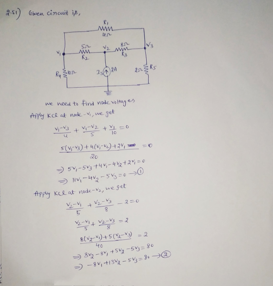
 Review Suppose that R1 = 6 Ω, R2 = 5 Ω, R3 = 8 Ω, R4 = 10 Ω, R5
= 2 Ω, and Is = 2 A. (Figure 1) Part A Find the node voltage v1
shown in the figure. Express your answer to three significant
figures and include the appropriate units. TemplatesSymbols
undoredoresetkeyboard shortcutshelp v1 v 1 = nothing nothing
Request Answer
P 2.51 3 K4 of 23 Part A Review Find the node voltage shown in the...
Review Suppose that R1 = 6 Ω, R2 = 5 Ω, R3 = 8 Ω, R4 = 10 Ω, R5
= 2 Ω, and Is = 2 A. (Figure 1) Part A Find the node voltage v1
shown in the figure. Express your answer to three significant
figures and include the appropriate units. TemplatesSymbols
undoredoresetkeyboard shortcutshelp v1 v 1 = nothing nothing
Request Answer
P 2.51 3 K4 of 23 Part A Review Find the node voltage shown in the...
 In the figure below, R1=212, R2=3.77 12, R3=1.85 82, R4=1 S2, R5=1 S2, R6=322. What is the total resistance between point A and B? Image size: SML Max Αον 220 6 BOW Please enter a numerical answer below. Accepted formats are numbers or "e" based scientific notation e.g. 0.23.-2, 106, 5.23e-8 Enter answer here
 RESISTOR VALUES: R1=1k, R2=2k, R3=3k, R4=3.9k, R5=5.1k, R6=6.2k,
R7=6.8K
NUMBERS: 2, 4, & 5
1 Short AB, as shown in Figure 3 - 2 (a). Use mesh analysis to calculate the voltage across each resistor and the current through AB, IAB 2. Leave AB open, as shown in Figure 3 - 2 (b). Use nodal analysis to calculate the voltage across each resistor as well as the voltage across AB, VAB 3. Find Thevenin's and Norton's Equivalent using the results...
RESISTOR VALUES: R1=1k, R2=2k, R3=3k, R4=3.9k, R5=5.1k, R6=6.2k,
R7=6.8K
NUMBERS: 2, 4, & 5
1 Short AB, as shown in Figure 3 - 2 (a). Use mesh analysis to calculate the voltage across each resistor and the current through AB, IAB 2. Leave AB open, as shown in Figure 3 - 2 (b). Use nodal analysis to calculate the voltage across each resistor as well as the voltage across AB, VAB 3. Find Thevenin's and Norton's Equivalent using the results...
 Question 3. (10 points) Four resistors are connected as shown in Figure 28.9a Find the equivalent resistance between a and c. R1-16 and R4-12 Ω R2-13 R3-4 (a) (b) What is the current in each resistor if a potential difference of 0.64 V is maintained between a and c. Calculate the current in each resistor I (for Ri resistor)- I (for R2 resistor)- I (for R3 resistor) I (for R4 resistor)- Which resistor uses more power, R or R4? Which...
 Question I : Consider the amplifier circuit shown below (p-150 for both transistors) (18 marks) +12V R4 1k8 R1 15k Q1 2N3904 C2+ 10μ R2 6V 4k7 2mA Out Q2 2N3904 C1 R3 10k R5 1k8 In 10H (i) Perform DC analysis and prove that the indicated voltages and currents in the figure are correctly calculated. Find the operating point of Q1 and Q2 (5 marks) (ii) Calculate the gain of this amplifier (5 marks) (iii) In the lab, only...
Most questions answered within 3 hours.
-
(Expected rate of return and risk) Carter Inc. is evaluating a
security. Calculate the investment’s expected...
asked 1 hour ago -
What specific indicators can point to lack of progress for
African Americans in American society?
asked 2 hours ago -
1-The Electrons in a beam are moving at 2.7×10⁸ m/s in an
electric field of 15000...
asked 2 hours ago -
A gas tank is a vertical cylinder. It has a radius of 1m, a
height of...
asked 3 hours ago -
Accent Software faces the following conditions. All of these
support Accent’s use of a market-penetration pricing...
asked 4 hours ago -
A mathematically inclined friend emails you the following
instructions: "Meet me in the cafeteria the first...
asked 4 hours ago -
A monopoly sells in two countries . The demand curves in the two
countries are p1...
asked 5 hours ago -
A .15kg rubber ball is bounced off a wall. Before hitting the
wall, the ball moves...
asked 5 hours ago -
A manufacturing company preparing to build a new plant is
considering three potential locations for it....
asked 5 hours ago -
B. If compound Y has approximately the same values of solubility
in toluene as compound X,...
asked 6 hours ago -
Oscar Inc. has inventory in Japan valued at 39,051,000 Yen one
year ago. One year ago...
asked 6 hours ago -
If Canada suffered from "fundamental disequilibrium," and its
government choose not to devalue its currency, a...
asked 6 hours ago