
Homework Answers


Add Answer to:
Part A The action of the two switches in the circuit seen in the figure is...
Circuit 1 Transient response of a series RLC circuit The two switches in the circuit in...
 Circuit 1 Transient response of a series RLC circuit The two switches in the circuit in Figure 8 operate synchronously. When switch 1 is in position "a", switch 2 is closed. When switch 1 is in position "b", switch 2 is open. Switch 1 has been in position "a" for a very long time. At 1-0, it moves instantaneously to position 4Ω t=0 2 8Ω 100mH 150V| 2Ω 60 V Figure 8: Circuit for Tasks 3 and 4 TASK 3...
QUESTION 1 The switch in the circuit seen in Figure has been in a position @...
 QUESTION 1 The switch in the circuit seen in Figure has been in a position @ for a long time. At t= 0 ,the switch moves instantaneously to position b AVM 10 kg 12.5 kg 120 (*) 150 kn ? 50 kn volt) = 40 nF ms Fill in the following values: Whent < 0: initial value Vc(0-) = When t = 0: Vo = When t > 0, time constant T = When t= 00, VF =D The final...
Problem 7.31 The switch in the circuit seen in the figure has been in position x...
 Problem 7.31 The switch in the circuit seen in the figure has been in position x for a long time. Att 0, the switch moves instantaneously to position y. (Figure 1) Part A Find ? so that the time constant for t > 0 is 40 ms a-Value Units Submit Request Answer Figure 1 of 1 Part B For the found ?, find t Express your answer in terms of t, where t is in seconds 20 k2 Ds 5...
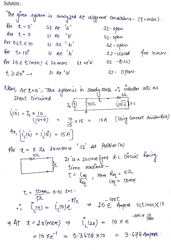
2. The two switches in the following circuit operate synchronously. When switch-1 is open switch-2 is...
 2. The two switches in the following circuit operate synchronously. When switch-1 is open switch-2 is in position a. When switch-1 is closed, switch-2 moves to position b. Switch been open for a long time and then closes at t-0. Find iz(t) for 120.(40) -1 has 5 0 o 51 1H (t) 8 V 1 H 5 H 24? a.
Problem 7.10 2 of 2 The switch in the circuit seen in the figure has been...
 Problem 7.10 2 of 2 The switch in the circuit seen in the figure has been in position 1 for a long time. Att 0, the switch moves instantaneously to position 2. (Figure 1) PartA Find the value of R so that 28 % of the initial energy stored in the 10 mH inductor is dissipated in R in 16 s Express your answer with the appropriate units. R- 1 Value Units Submit Request Answer Figure 1 of 1 Return...
USE differential Approach in your analysis The switch in the circuit has been in position 1...
 USE differential Approach in your analysis The switch in the circuit has been in position 1 for a long time. At t = 0 it moves instantaneously to position 2. (Figure 1) 10 12 50 VO 331 31.5 HŽ 402 How many milliseconds after the switch operates does v, equal 160 V ?
4. The switch in the circuit in the figure below has been in position 'a' for...
 4. The switch in the circuit in the figure below has been in position 'a' for a long time. At t = 0, the switch moves instantaneously to position b. For t> 0*, find a) vo(t) b) io(t). 5k12 b 10 k 12 11 = 0 + 10 kn} 1,040nF 40 kN 75 V 100 V
2. The switch in the circuit shown in Figure 1 has been in position 'a' for...
 2. The switch in the circuit shown in Figure 1 has been in position 'a' for a long time. At t=0, the switch moves instantaneously to position b. a) Find the numerical expression for io(t) when t > 0. b) Find the numerical expression for volt) fort > 0 1 = 0 b! 51 602 45 A 2150 vo 20 10 mH 240 V 1
Problem 4:Consider a circuit with two switches, one ideal battery, one resistor, one capacitor and one...
 Problem 4:Consider a circuit with two switches, one ideal battery, one resistor, one capacitor and one inductor. The circuit is drawn below with both switches open: R-14.00 C ; 6.20 uF, and L 54.0 mH, and the ideal battery has emf ξ . 34.0 V. At t-o, both switches are open and the charge on the capacitor is qlt-0) (a) The switch is put at position "a". Compute the charge, oft-S us), on the capacitor after 5.00 microseconds (5x10 sec)...
Problem 8.15 only please 8.15 The resistor in the circuit of Fig. P8.14 is increased from...
 Problem 8.15 only please
8.15 The resistor in the circuit of Fig. P8.14 is increased from 100 to 125 N. Find v(t) for t 0. PSPICE 8.14 The two switches in the circuit seen in Fig. P8.14 operate synchronously. When switch 1 is in position a, switch 2 is in position d. When switch 1 move to position b, switch 2 moves to position c. Switch 1 has been in position a for a long time. At t = 0,...
Problem 8.15 only please
8.15 The resistor in the circuit of Fig. P8.14 is increased from 100 to 125 N. Find v(t) for t 0. PSPICE 8.14 The two switches in the circuit seen in Fig. P8.14 operate synchronously. When switch 1 is in position a, switch 2 is in position d. When switch 1 move to position b, switch 2 moves to position c. Switch 1 has been in position a for a long time. At t = 0,...
 Circuit 1 Transient response of a series RLC circuit The two switches in the circuit in Figure 8 operate synchronously. When switch 1 is in position "a", switch 2 is closed. When switch 1 is in position "b", switch 2 is open. Switch 1 has been in position "a" for a very long time. At 1-0, it moves instantaneously to position 4Ω t=0 2 8Ω 100mH 150V| 2Ω 60 V Figure 8: Circuit for Tasks 3 and 4 TASK 3...
 QUESTION 1 The switch in the circuit seen in Figure has been in a position @ for a long time. At t= 0 ,the switch moves instantaneously to position b AVM 10 kg 12.5 kg 120 (*) 150 kn ? 50 kn volt) = 40 nF ms Fill in the following values: Whent < 0: initial value Vc(0-) = When t = 0: Vo = When t > 0, time constant T = When t= 00, VF =D The final...
 Problem 7.31 The switch in the circuit seen in the figure has been in position x for a long time. Att 0, the switch moves instantaneously to position y. (Figure 1) Part A Find ? so that the time constant for t > 0 is 40 ms a-Value Units Submit Request Answer Figure 1 of 1 Part B For the found ?, find t Express your answer in terms of t, where t is in seconds 20 k2 Ds 5...
 2. The two switches in the following circuit operate synchronously. When switch-1 is open switch-2 is in position a. When switch-1 is closed, switch-2 moves to position b. Switch been open for a long time and then closes at t-0. Find iz(t) for 120.(40) -1 has 5 0 o 51 1H (t) 8 V 1 H 5 H 24? a.
 Problem 7.10 2 of 2 The switch in the circuit seen in the figure has been in position 1 for a long time. Att 0, the switch moves instantaneously to position 2. (Figure 1) PartA Find the value of R so that 28 % of the initial energy stored in the 10 mH inductor is dissipated in R in 16 s Express your answer with the appropriate units. R- 1 Value Units Submit Request Answer Figure 1 of 1 Return...
 USE differential Approach in your analysis The switch in the circuit has been in position 1 for a long time. At t = 0 it moves instantaneously to position 2. (Figure 1) 10 12 50 VO 331 31.5 HŽ 402 How many milliseconds after the switch operates does v, equal 160 V ?
 4. The switch in the circuit in the figure below has been in position 'a' for a long time. At t = 0, the switch moves instantaneously to position b. For t> 0*, find a) vo(t) b) io(t). 5k12 b 10 k 12 11 = 0 + 10 kn} 1,040nF 40 kN 75 V 100 V
 2. The switch in the circuit shown in Figure 1 has been in position 'a' for a long time. At t=0, the switch moves instantaneously to position b. a) Find the numerical expression for io(t) when t > 0. b) Find the numerical expression for volt) fort > 0 1 = 0 b! 51 602 45 A 2150 vo 20 10 mH 240 V 1
 Problem 4:Consider a circuit with two switches, one ideal battery, one resistor, one capacitor and one inductor. The circuit is drawn below with both switches open: R-14.00 C ; 6.20 uF, and L 54.0 mH, and the ideal battery has emf ξ . 34.0 V. At t-o, both switches are open and the charge on the capacitor is qlt-0) (a) The switch is put at position "a". Compute the charge, oft-S us), on the capacitor after 5.00 microseconds (5x10 sec)...
 Problem 8.15 only please
8.15 The resistor in the circuit of Fig. P8.14 is increased from 100 to 125 N. Find v(t) for t 0. PSPICE 8.14 The two switches in the circuit seen in Fig. P8.14 operate synchronously. When switch 1 is in position a, switch 2 is in position d. When switch 1 move to position b, switch 2 moves to position c. Switch 1 has been in position a for a long time. At t = 0,...
Problem 8.15 only please
8.15 The resistor in the circuit of Fig. P8.14 is increased from 100 to 125 N. Find v(t) for t 0. PSPICE 8.14 The two switches in the circuit seen in Fig. P8.14 operate synchronously. When switch 1 is in position a, switch 2 is in position d. When switch 1 move to position b, switch 2 moves to position c. Switch 1 has been in position a for a long time. At t = 0,...
Most questions answered within 3 hours.
-
lease solve all the
questions, don't need to explanations
Q1 - All animal
species have general...
asked 4 hours ago -
Business Phasing
1.Discuss the logical progression for growing a business, which
starts from the initial idea...
asked 4 hours ago -
Modify
When executing on the command line having only
this program name, the program will accept...
asked 5 hours ago -
Kenny Electric Company's noncallable bonds were issued several
years ago and now have 20 years to...
asked 6 hours ago -
find H(e^Jtheta) at theta= 0, pi/10, pi/20, pi/2 for
the following:
a) H(e^Jtheta)= 1+e^Jtheta
b) H(e^Jtheta)=...
asked 6 hours ago -
Home Corporation will open a new store on January 1. Based on
experience from its other...
asked 6 hours ago -
In a neoclassical model, use the IS-LM to analyze the effect of
a permanent money supply...
asked 7 hours ago -
An electron passes through a point 2.67 cm from a long straight
wire as it moves...
asked 8 hours ago -
A grammar is a 4-tuple G, G = (Ν, Σ, Π, Σ, S) where, Ν is...
asked 8 hours ago -
In this part, calculate the present values. Use the Excel PV
function to compute the present...
asked 8 hours ago -
Part 1. Primitive Types, Sorting, Recursion for
Homework.java
a) Implement the static method initializeArray that receives...
asked 9 hours ago -
Using C++, build a sorter that can rank a sequence of numbers in
a descending order....
asked 9 hours ago