
Homework Answers
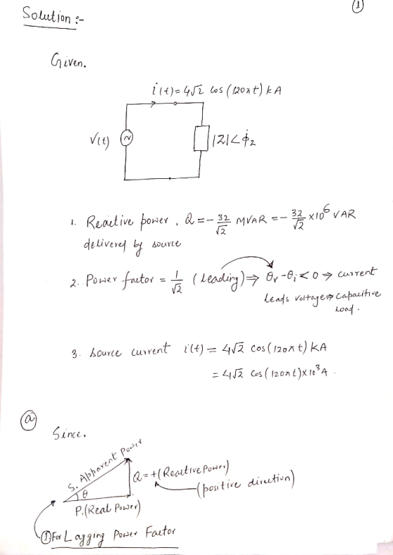
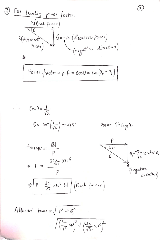
Leading p.f. means , current leads voltage=>capacitive load.


Add Answer to:
1SL 1. (30%). A single-phase source is applied to a two terminal passive circuit with equivalent...
Problem 1 A single-phase source is supplying passive loads through two wires. The impedance of each...
 Problem 1 A single-phase source is supplying passive loads through two wires. The impedance of each wire is (0.05 + 30.05) 2. The load is connected between the two wires at the far end. The load current is 75 A (rms). a. What is the source voltage that you need in order to have 120 V (rms) across the load when the power factor of the load is unity? b. Repeat for the case where the load power factor is...
The single-phase circuit shown in Figure. 1 is operating at steady-state. R;=1000 G=10F L=0.05 H C...
 The single-phase circuit shown in Figure. 1 is operating at steady-state. R;=1000 G=10F L=0.05 H C = 2001F1 ZL.+0.2H R=2002} @va Vs1 V2*10000/10000) M Vs2 V2200Cos(1000+30) M Figure. 1: Single-Phase Circuit 1. Represent the circuit in the phasor domain. Show the impedance value for each passive component of the circuit and the phasor value for each voltage source. 2. Using the circuit in phasor domain calculate the value of each branch current and the complex, apparent, active, and reactive powers...
Consider a single-phase circuit where a 14 kV, 60 Hz voltage source feeds an electric load...
 Consider a single-phase circuit where a 14 kV, 60 Hz voltage source feeds an electric load through a feeder whose impedance is 1.5 + j 3 Ω. The load is known to consume 4 MW and 3 MVAR. Let V and δ represent the rms voltage and its phase angle (relative to the source voltage) at the load terminals. Two equations are needed to solve for V and δ. 1) Derive two analytical expressions in terms of V and δ...
A three-phase line, which has an impedance of (2 + j4) Ω per phase, feeds two...
A three-phase line, which has an impedance of (2 + j4) Ω per phase, feeds two balanced three-phase loads that are connected in parallel. One of the loads is Y- connected with an impedance of (30 + j40) Ω per phase, and the other is delta- connected with an impedance of (60 + j45) Ω per phase. The line is energized at the sending end from a 60-Hz, three phase, balanced voltage source of 120√3 V (rms, line- to-line). Determine...
P3- A source supplies power to the following three load connected in parallel: (1) a light...
 P3- A source supplies power to the following three load connected in parallel: (1) a light load drawing 20 kW, (2) an induction motor drawing 10 KVA at 0.90 power factor lagging, and (3) a synchronous motor operating at 10 hp, 85% efficiency and 0.95 power factor leading (1 hp = 0.746 kW), Determine the real, reactive, and apparent power delivered by the source. Also, draw the source power triangle.
P3- A source supplies power to the following three load connected in parallel: (1) a light...
 P3- A source supplies power to the following three load connected in parallel: (1) a light load drawing 20 kW. (2) an induction motor drawing 10 kVA at 0.90 power factor lagging, and (3) a synchronous motor operating at 10 hp, 85% efficiency and 0.95 power factor leading (1 hp = 0.746 kW). Determine the real, reactive, and apparent power delivered by the source. Also, draw the source power triangle.
solve the circuit following the steps For the sample AC circuit 2: vst) 31H Zeq Vs(t)...
 solve the circuit following the steps
For the sample AC circuit 2: vst) 31H Zeq Vs(t) = 10 cos (10t + 90°) V (Variations: Changes in resistor and source values and directions).) B. Determine Step 1: The voltage phasor VSF Step 2: The equivalent impedance Zeq Step 3: The phasor current IF Step 4: The steady state current l(t)ss Step 5: The complex power (S = VsFlF* = P + jQ). Step 6: The average (P) and reactive power (Q)....
solve the circuit following the steps
For the sample AC circuit 2: vst) 31H Zeq Vs(t) = 10 cos (10t + 90°) V (Variations: Changes in resistor and source values and directions).) B. Determine Step 1: The voltage phasor VSF Step 2: The equivalent impedance Zeq Step 3: The phasor current IF Step 4: The steady state current l(t)ss Step 5: The complex power (S = VsFlF* = P + jQ). Step 6: The average (P) and reactive power (Q)....
I. Two electric loads are connected in parallel to a source of value u(t) = 300...
 I. Two electric loads are connected in parallel to a source of value u(t) = 300 cos(380t) V. The first load absorbs 3 kW at a power factor of 0.5 lagging. The second load absorbs 4kW at a power factor of 0.8 leading. (a) Find the current I through the first load. (b) Find the total current I c) Find the total apparent power (d) Find the total average power e) Find the overall power factor of the two loads...
The three loads in the circuit seen in Fig.1 are Si 6+j3 kVA, S2-7.5 Kw and...
 The three loads in the circuit seen in Fig.1 are Si 6+j3 kVA, S2-7.5 Kw and 0 9 leading power factor and S -9 kVA and a unity power factor. a) Calculate the complex power associated with each voltage source, and b) Verify that the total real and reactive power delivered by the sources equals the total real and reactive power absorbed by the network. c) What is the element can be connected at the terminals of Vgl to let...
The three figures below show a balanced three phase Delta, its Wye equivalent and the single...
 The three figures below show a balanced three phase Delta, its Wye equivalent and the single phase equivalent of the three phase Wye. All three representations have a complex load ZALD or ZYLD and a complex line impedance ZLINE Refer to these diagrams when answering questions 1-4. ZLINE Vab= 679 L 30° ZLINE ZALD ZLINE = 2+1 DELTA ZALD= 18+24j2 LINE ZLINE ZLINE ZYLD 7yun WYE WYE ZYLD ZLINE ZLINE Van Complex Load ZYLD Single Line WYE 1) In the...
 Problem 1 A single-phase source is supplying passive loads through two wires. The impedance of each wire is (0.05 + 30.05) 2. The load is connected between the two wires at the far end. The load current is 75 A (rms). a. What is the source voltage that you need in order to have 120 V (rms) across the load when the power factor of the load is unity? b. Repeat for the case where the load power factor is...
 The single-phase circuit shown in Figure. 1 is operating at steady-state. R;=1000 G=10F L=0.05 H C = 2001F1 ZL.+0.2H R=2002} @va Vs1 V2*10000/10000) M Vs2 V2200Cos(1000+30) M Figure. 1: Single-Phase Circuit 1. Represent the circuit in the phasor domain. Show the impedance value for each passive component of the circuit and the phasor value for each voltage source. 2. Using the circuit in phasor domain calculate the value of each branch current and the complex, apparent, active, and reactive powers...
 Consider a single-phase circuit where a 14 kV, 60 Hz voltage source feeds an electric load through a feeder whose impedance is 1.5 + j 3 Ω. The load is known to consume 4 MW and 3 MVAR. Let V and δ represent the rms voltage and its phase angle (relative to the source voltage) at the load terminals. Two equations are needed to solve for V and δ. 1) Derive two analytical expressions in terms of V and δ...
 P3- A source supplies power to the following three load connected in parallel: (1) a light load drawing 20 kW, (2) an induction motor drawing 10 KVA at 0.90 power factor lagging, and (3) a synchronous motor operating at 10 hp, 85% efficiency and 0.95 power factor leading (1 hp = 0.746 kW), Determine the real, reactive, and apparent power delivered by the source. Also, draw the source power triangle.
 P3- A source supplies power to the following three load connected in parallel: (1) a light load drawing 20 kW. (2) an induction motor drawing 10 kVA at 0.90 power factor lagging, and (3) a synchronous motor operating at 10 hp, 85% efficiency and 0.95 power factor leading (1 hp = 0.746 kW). Determine the real, reactive, and apparent power delivered by the source. Also, draw the source power triangle.
 solve the circuit following the steps
For the sample AC circuit 2: vst) 31H Zeq Vs(t) = 10 cos (10t + 90°) V (Variations: Changes in resistor and source values and directions).) B. Determine Step 1: The voltage phasor VSF Step 2: The equivalent impedance Zeq Step 3: The phasor current IF Step 4: The steady state current l(t)ss Step 5: The complex power (S = VsFlF* = P + jQ). Step 6: The average (P) and reactive power (Q)....
solve the circuit following the steps
For the sample AC circuit 2: vst) 31H Zeq Vs(t) = 10 cos (10t + 90°) V (Variations: Changes in resistor and source values and directions).) B. Determine Step 1: The voltage phasor VSF Step 2: The equivalent impedance Zeq Step 3: The phasor current IF Step 4: The steady state current l(t)ss Step 5: The complex power (S = VsFlF* = P + jQ). Step 6: The average (P) and reactive power (Q)....
 I. Two electric loads are connected in parallel to a source of value u(t) = 300 cos(380t) V. The first load absorbs 3 kW at a power factor of 0.5 lagging. The second load absorbs 4kW at a power factor of 0.8 leading. (a) Find the current I through the first load. (b) Find the total current I c) Find the total apparent power (d) Find the total average power e) Find the overall power factor of the two loads...
 The three loads in the circuit seen in Fig.1 are Si 6+j3 kVA, S2-7.5 Kw and 0 9 leading power factor and S -9 kVA and a unity power factor. a) Calculate the complex power associated with each voltage source, and b) Verify that the total real and reactive power delivered by the sources equals the total real and reactive power absorbed by the network. c) What is the element can be connected at the terminals of Vgl to let...
 The three figures below show a balanced three phase Delta, its Wye equivalent and the single phase equivalent of the three phase Wye. All three representations have a complex load ZALD or ZYLD and a complex line impedance ZLINE Refer to these diagrams when answering questions 1-4. ZLINE Vab= 679 L 30° ZLINE ZALD ZLINE = 2+1 DELTA ZALD= 18+24j2 LINE ZLINE ZLINE ZYLD 7yun WYE WYE ZYLD ZLINE ZLINE Van Complex Load ZYLD Single Line WYE 1) In the...
Most questions answered within 3 hours.
-
suppose there is a normally distributed population with a mean of
250 and a standard deviation...
asked 18 minutes ago -
Question Three
Suppose you as project manager are using the Waterfall
development methodology on a large...
asked 1 hour ago -
Which statement is not true about welfare in Canada?
A.Benefits typically vary based on one's ability...
asked 1 hour ago -
Please help me with FLOWCHART and UML diagram for class,
thank you!
#include <iostream>
#include <fstream>...
asked 2 hours ago -
3. Describe the “logic circuit” of the Lac operon. Which
proteins are bound or not to...
asked 2 hours ago -
Ayesha’s adjusted gross income is $60,000 in 2019. She donated a
piece of artwork with a...
asked 2 hours ago -
For Dijkstra’s shortest path algorithm:
a. Give the Big-O time for Dijkstra’s shortest path algorithm
and...
asked 2 hours ago -
Phosphorus violates the 'octet rule' in biological molecules,
forming more covalent bonds than expected based on...
asked 2 hours ago -
A 1.3 eV electron has a 10-4 probability of tunneling
through a 2.4 eV potential barrier....
asked 3 hours ago -
What is the one ingredient that is common to being successful
with all stakeholders?
profit
trust...
asked 3 hours ago -
Write an assembly language 32 bit program that reads in lines of
text by a .txt...
asked 3 hours ago -
what is the density ( in g/L) of hydrogen gas at 29 degrees C and a...
asked 3 hours ago