
Homework Answers

Add Answer to:
Op Amp Integrators and Differentiators 1.) Design an op-amp circuit that acts as an integrator. Chose...
A. Consider the circuit in Figure 7.1 to be an op amp integrator. Using the ideal op amp model and KCL, show that:
 A. Consider the circuit in Figure 7.1 to be an op amp integrator. Using the ideal op amp model and KCL, show that:B. If Vin is a square wave, what will the shape of Vout be? C. If Vin is a triangle wave, what will the shape of Vout be? D. If Vin is a sine wave, what will the shape of Vout be? E. Now consider the circuit in Figure 7.1 to be an active low-pass filter. Show that the amplitude response...
Inverting Amplifier Figure 4.2 shows the fundamental configuration of Op-Amp in which it is used as...
 Inverting Amplifier Figure 4.2 shows the fundamental configuration of Op-Amp in which it is used as an inverting amplifier. In this configuration the ratio, R2/R1 completely controls the effective gain of the amplifier and it can be verified that the output voltage is equal to Vo = - (R2/R1)Vin R2 100K Q-10V R1 Vinow 20K 1 2 7 V Vo 3 -10v Figure 4.2 Part 1 - Inverting Amp: Procedure 1. Construct the circuit of figure 4.2 using Op-Amp IC...
The virtual Op-amp is found in the group Analog/ Analog_Virtual/ Op-amp_3T_Virtual. Look carefully at the symbol...
 The virtual Op-amp is found in the group Analog/ Analog_Virtual/
Op-amp_3T_Virtual. Look carefully at the symbol for the Op Amp. Be
careful not to confuse the terminal labeled – with the one labeled
+. The gain of the circuit is . Measure and record the
output on the multi-meter. Change R1 to 5kΩ and then to 10kΩ, in
both cases measure and record the output on the multi-meter. Do
your results match what you expect from the formula?
R1 =...
The virtual Op-amp is found in the group Analog/ Analog_Virtual/
Op-amp_3T_Virtual. Look carefully at the symbol for the Op Amp. Be
careful not to confuse the terminal labeled – with the one labeled
+. The gain of the circuit is . Measure and record the
output on the multi-meter. Change R1 to 5kΩ and then to 10kΩ, in
both cases measure and record the output on the multi-meter. Do
your results match what you expect from the formula?
R1 =...
1. Design an op-amp integrator with input resistance 50kΩ and time constant 0.2ms. Sketch the circuit,...
1. Design an op-amp integrator with input resistance 50kΩ and time constant 0.2ms. Sketch the circuit, including reasonable component values. Sketch the Bode plot for the filter. What type of filter is this (LP, HP, BP. Or notch)? What problems does this filter suffer from in practice? 2. Design a circuit which will implement the following mathematical operation. V1, V2,V3, and V4 represent input voltages. Your final answer should be a circuit with reasonable resistor values. V0 = V1 +...
Design an op-amp circuit using 741 op-amps to do the following; Input range: -300mV to 100mV...
Design an op-amp circuit using 741 op-amps to do the following; Input range: -300mV to 100mV (note the input is 400mVpp sine wave with 100mV offset) output range: 0V to 5V (Note: a -300mV input should generate a 0V output and a 100mV input should generate a +5V output.) Please use the free online versions of Multisim or PartSim.
2. Design a non-inverting op-amp circuit with two resistors under the following conditions: a. The gain of the ampl...
 2. Design a non-inverting op-amp circuit with two resistors under the following conditions: a. The gain of the amplifier must be +10 b. The input range is ± 2V c. The total power consumed by the resistors must be less than 100 mW Show all the calculations required to design the amplifier circuit with the shown specifications.in details Use MULTISIM to create the op-amp circuit and print a fully labelled diagram of the circuits with the voltmeters displays showing both...
1- Design a lossy integrator op-amp circuit using op-amp 741. First, derive an expression for - V...
 UPLOAD PSPICE SIMULATION TO VERIFY CALCULATIONS
1- Design a lossy integrator op-amp circuit using op-amp 741. First, derive an expression for - Vo Then assign values to circuit components in order to have Gai 1. Verify your design with a PSpice simulation. Since gain value depends on Vi frequency, perform an AC sweep analysis (frequency response) to obtain which frequency gives you this gain. Report this trequency. IVil
1- Design a lossy integrator op-amp circuit using op-amp 741. First, derive...
UPLOAD PSPICE SIMULATION TO VERIFY CALCULATIONS
1- Design a lossy integrator op-amp circuit using op-amp 741. First, derive an expression for - Vo Then assign values to circuit components in order to have Gai 1. Verify your design with a PSpice simulation. Since gain value depends on Vi frequency, perform an AC sweep analysis (frequency response) to obtain which frequency gives you this gain. Report this trequency. IVil
1- Design a lossy integrator op-amp circuit using op-amp 741. First, derive...
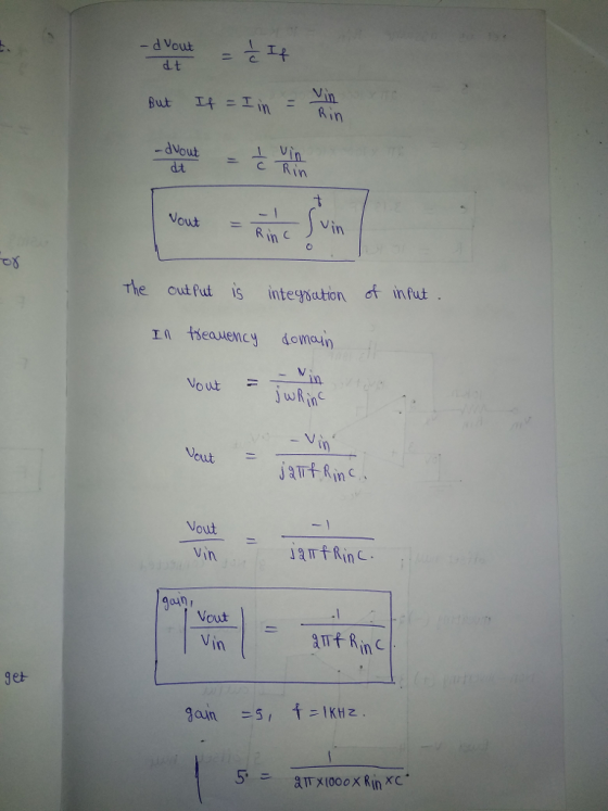
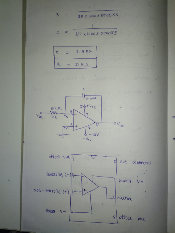
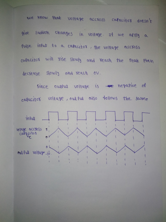
2.90 An op-amp differentiator, employing the circuit shown in Fig. 2.27(a), has R 10 k2 and C 0.1...
 2.90 An op-amp differentiator, employing the circuit shown in Fig. 2.27(a), has R 10 k2 and C 0.1 uF. When a triangle wave of Łl-V peak amplitude at 1 kHz is applied to the input, what form of output results? What is its fre- quency? What is its peak amplitude? What is its average value? What value of R is needed to cause the output to have a 10-V peak amplitude?
2.90 An op-amp differentiator, employing the circuit shown in...
2.90 An op-amp differentiator, employing the circuit shown in Fig. 2.27(a), has R 10 k2 and C 0.1 uF. When a triangle wave of Łl-V peak amplitude at 1 kHz is applied to the input, what form of output results? What is its fre- quency? What is its peak amplitude? What is its average value? What value of R is needed to cause the output to have a 10-V peak amplitude?
2.90 An op-amp differentiator, employing the circuit shown in...
5- The input to the circuit of problem 1 is a 10 kHz square wave with...
5- The input to the circuit of problem 1 is a 10 kHz square wave with a peak-to-peak amplitude of 2 V and rise and fall times of 1 µs. Sketch the output waveform if the op amp used is a µA741. 6. Repeat 5 if the op amp is an LM318.
Op-Amp Circuit Stability Although op-amps behave as single-pole amplifiers which are "uncondition...
 Op-Amp Circuit Stability Although op-amps behave as single-pole amplifiers which are "unconditionally stable," it's still possible to make unstable amplifiers if you don't know what you're doing. The most famous example of this is the voltage differentiator 1. Consider the following circuit: a. Find the expression for this amplifier's ideal gain Aco (s), assuming the op-amp is ideal (a(s) - o. Hint: It's just an inverting amplifier with z and z2 R (5pts) b. Suppose the gain-setting components have values...
 Inverting Amplifier Figure 4.2 shows the fundamental configuration of Op-Amp in which it is used as an inverting amplifier. In this configuration the ratio, R2/R1 completely controls the effective gain of the amplifier and it can be verified that the output voltage is equal to Vo = - (R2/R1)Vin R2 100K Q-10V R1 Vinow 20K 1 2 7 V Vo 3 -10v Figure 4.2 Part 1 - Inverting Amp: Procedure 1. Construct the circuit of figure 4.2 using Op-Amp IC...
 The virtual Op-amp is found in the group Analog/ Analog_Virtual/
Op-amp_3T_Virtual. Look carefully at the symbol for the Op Amp. Be
careful not to confuse the terminal labeled – with the one labeled
+. The gain of the circuit is . Measure and record the
output on the multi-meter. Change R1 to 5kΩ and then to 10kΩ, in
both cases measure and record the output on the multi-meter. Do
your results match what you expect from the formula?
R1 =...
The virtual Op-amp is found in the group Analog/ Analog_Virtual/
Op-amp_3T_Virtual. Look carefully at the symbol for the Op Amp. Be
careful not to confuse the terminal labeled – with the one labeled
+. The gain of the circuit is . Measure and record the
output on the multi-meter. Change R1 to 5kΩ and then to 10kΩ, in
both cases measure and record the output on the multi-meter. Do
your results match what you expect from the formula?
R1 =...
 2. Design a non-inverting op-amp circuit with two resistors under the following conditions: a. The gain of the amplifier must be +10 b. The input range is ± 2V c. The total power consumed by the resistors must be less than 100 mW Show all the calculations required to design the amplifier circuit with the shown specifications.in details Use MULTISIM to create the op-amp circuit and print a fully labelled diagram of the circuits with the voltmeters displays showing both...
 UPLOAD PSPICE SIMULATION TO VERIFY CALCULATIONS
1- Design a lossy integrator op-amp circuit using op-amp 741. First, derive an expression for - Vo Then assign values to circuit components in order to have Gai 1. Verify your design with a PSpice simulation. Since gain value depends on Vi frequency, perform an AC sweep analysis (frequency response) to obtain which frequency gives you this gain. Report this trequency. IVil
1- Design a lossy integrator op-amp circuit using op-amp 741. First, derive...
UPLOAD PSPICE SIMULATION TO VERIFY CALCULATIONS
1- Design a lossy integrator op-amp circuit using op-amp 741. First, derive an expression for - Vo Then assign values to circuit components in order to have Gai 1. Verify your design with a PSpice simulation. Since gain value depends on Vi frequency, perform an AC sweep analysis (frequency response) to obtain which frequency gives you this gain. Report this trequency. IVil
1- Design a lossy integrator op-amp circuit using op-amp 741. First, derive...
 2.90 An op-amp differentiator, employing the circuit shown in Fig. 2.27(a), has R 10 k2 and C 0.1 uF. When a triangle wave of Łl-V peak amplitude at 1 kHz is applied to the input, what form of output results? What is its fre- quency? What is its peak amplitude? What is its average value? What value of R is needed to cause the output to have a 10-V peak amplitude?
2.90 An op-amp differentiator, employing the circuit shown in...
2.90 An op-amp differentiator, employing the circuit shown in Fig. 2.27(a), has R 10 k2 and C 0.1 uF. When a triangle wave of Łl-V peak amplitude at 1 kHz is applied to the input, what form of output results? What is its fre- quency? What is its peak amplitude? What is its average value? What value of R is needed to cause the output to have a 10-V peak amplitude?
2.90 An op-amp differentiator, employing the circuit shown in...
 Op-Amp Circuit Stability Although op-amps behave as single-pole amplifiers which are "unconditionally stable," it's still possible to make unstable amplifiers if you don't know what you're doing. The most famous example of this is the voltage differentiator 1. Consider the following circuit: a. Find the expression for this amplifier's ideal gain Aco (s), assuming the op-amp is ideal (a(s) - o. Hint: It's just an inverting amplifier with z and z2 R (5pts) b. Suppose the gain-setting components have values...
Most questions answered within 3 hours.
-
Do not neglect the old for the new. The existing business must
not lose priority simply...
asked 28 minutes ago -
Kylie is a single mom with two dependent children,
Tanner, age 7 and Olivia, age 11....
asked 1 hour ago -
Phosphorous + bromine = phosphorous tribromide. If 35.0 g of
bromine are reacted and 27.9 grams...
asked 3 hours ago -
Derive the long wavelength limit of the Planck energy density
distribution
asked 3 hours ago -
Calculate the pH of each of the following solutions.
0.50 M HBr
3.1×10⁻⁴ M KOH
4.2×10⁻⁵...
asked 6 hours ago -
For the year ended December 31, Depot Max’s cost of merchandise
sold was $85,600. Inventory at the...
asked 6 hours ago -
Week 10 - Professional Memo Assignment
Professional Memo Assignment
Your mission for this week, should you...
asked 6 hours ago -
Write a Python program that stores the data for each
player on the team, and it...
asked 6 hours ago -
In
the last 3 months, mike never knows when he is going to get his
allowance...
asked 7 hours ago -
Is Ca(OH)2 a Bronsted base, Lewis base, or both? Why?
asked 7 hours ago -
1A- Why don’t voters complain about U.S. tariffs on imported
sugar?
Because sugar is only a...
asked 7 hours ago -
Cash Payback Period
Primera Banco is evaluating two capital investment proposals for
a drive-up ATM kiosk,...
asked 7 hours ago