

Homework Answers


Add Answer to:
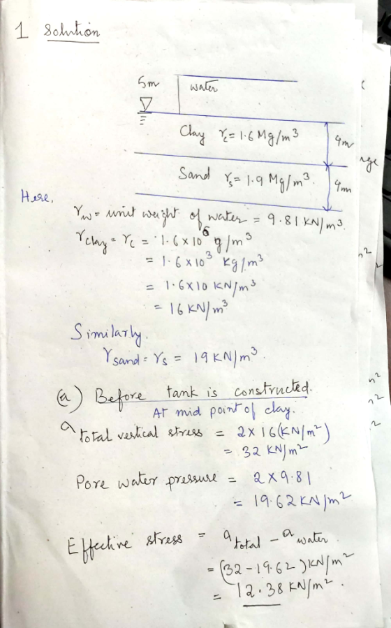
1. A large tank structure 5 m high is to be constructed on the site as...
Question 5 (Effective Stress & Consolidation) Figure 05 shows the soil profile of a construction site....
 Question 5 (Effective Stress & Consolidation) Figure 05 shows the soil profile of a construction site. The water table is at the ground surface. Saturated unit weight of the sand is 18.8kN/m' and that of the clay is 19.6kN/m. Assume permeability of the clay is very low and unit weight of water is 10kN/m'. Water Table Sand 5m Clay 6m Figure 05 a) Determine the vertical total stress, pore water pressure, and vertical effective stress at the mid-height of the...
A circular tank of 6 m diameter is to be constructed at a site with the...
 A circular tank of 6 m diameter is to be constructed at a site with the soil profile (2 m sand overlying 4 m clay) shown in Figure 3 below. The water table is 2 m below the surface (i.e. at the sand-clay interface). The circular tank will apply a loading of 200 kN/m2 Circular tank - (z = 0 m) Sand (z 2 m) Pt A (z 3 m) Clay (z 4 m) Pt B (z 5 m) (z...
A levee is constructed atop a 3m thick clay layer resting atop a sand layer. During...
 A levee is constructed atop a 3m thick clay layer resting atop a sand layer. During a storm event, the levee retains water and the soil at the bottom of the channel is sand that is hydraulically connected to the sand beneath the clay. Head loss in the sand layer is negligible (i.e., the total head at point A is the same as the total head at point B), and water flows vertically upward through the clay. The water table...
geotechnical engineering The soil profile at a site consists of a clay layer 10 m thick,...
 geotechnical engineering
The soil profile at a site consists of a clay layer 10 m thick, sandwich between two sand layers. The top sand layer has a density of 1.9 Mg/m² and is 5 m thick. Below this layer is a 10 m thick clay layer with a saturated density of 1.8 Mg/m' and a saturated water content 42%. The deeper sand layer has a saturated density of 1.9 Mg/m² and extend to the depth investigated at the site. The...
geotechnical engineering
The soil profile at a site consists of a clay layer 10 m thick, sandwich between two sand layers. The top sand layer has a density of 1.9 Mg/m² and is 5 m thick. Below this layer is a 10 m thick clay layer with a saturated density of 1.8 Mg/m' and a saturated water content 42%. The deeper sand layer has a saturated density of 1.9 Mg/m² and extend to the depth investigated at the site. The...
[Problems 1-4] The soil profile at a site for a proposed office building consists of a...
 [Problems 1-4] The soil profile at a site for a proposed office building consists of a layer of fine sand 10.4 m thick above a layer of soft, normally consolidated clay 2 m thick. Below the soft clay is a deposit of coarse sand. The groundwater table was observed at 3 m below ground level. The void ratio of the sand is 0.76, and the water content of the clay is 43%. The building will impose a vertical stress increase...
Question 3c, how was the effective stress calculated for the depth of 2,6 and 10 m?...
 Question 3c, how was the effective stress calculated for the
depth of 2,6 and 10 m? How was the Cp calculated? Is sigma 1 the
effective stress? What is sigma? Why d is 4?
1 3c In ε- Cp w-Σε disp ε. d do initial o Deformation depth d Strain (-) (m) 4 176.2 1.08 2 62 0.27 6 107 4 128.4 0.16 0.63 152 4 10 95.5 0.10 0.39 total 2.10 in 3) A 10 m wide and very...
Question 3c, how was the effective stress calculated for the
depth of 2,6 and 10 m? How was the Cp calculated? Is sigma 1 the
effective stress? What is sigma? Why d is 4?
1 3c In ε- Cp w-Σε disp ε. d do initial o Deformation depth d Strain (-) (m) 4 176.2 1.08 2 62 0.27 6 107 4 128.4 0.16 0.63 152 4 10 95.5 0.10 0.39 total 2.10 in 3) A 10 m wide and very...
1. A 2 m high road embankment is to be constructed in order to raise the...
 1. A 2 m high road embankment is to be constructed in order to raise the level of a road above the potential flood level. Consider the data shown on Figure 1 and determine the vertical effective stress (ov) at Points X and Y (which are at the centre of the two soil layers) (i) before the road is constructed, (ii) immediately after construction of the road embankment and (iii) many years later. . . . . . . ....
3) At a construction site, a site investigation has been carried out. At ground level (-1...
 3) At a construction site, a site investigation has been carried out. At ground level (-1 m NAP) a clay layer with a thickness of 4 m is found (y = 16 kN/m”, k = 2.0x10⁻¹² m/s, Cp = 15), followed by a sand layer of 6 m thickness (y = 20 kN/m², k = 5.0x10⁻⁷ m/s), another clay layer of 4m thickness (y = 18 kN/m3, k = 4.5x10⁻¹¹ m/s, Cp = 25), and finally another sand layer (y...
1. An 8-m thick normally consolidated clay layer is doubly drained as shown below. (This means...
 1. An 8-m thick normally consolidated clay layer is doubly drained as shown below. (This means that a very pervious layer compared to the clay exists on top of and under the clay layer) The embankment applied an average vertical stress increase of 100 kPa to the clay layer. The water table is located at the mid depth of the sand layer. Assume the sand above the water table is dry 0 Pore water pressure, u (kPa) 20 40 60...
Q2. A borehole at a site reveals the soil profile shown in Figure 2. Plot the...
 Q2. A borehole at a site reveals the soil profile shown in Figure 2. Plot the distribution of vertical total and effective stresses with depth. Assume pore air pressure is zero and the pore-water pressure due to capillarity is negative as shown in Figure 3 Elevation (m) Very fine wet sand with silt w=596, S = 40% Fine sand saturated by capillary action Fine sand, 12% 2.0 5.4 Soft blue clay, w= 28% 20.6 Figure 2 Soil Porewater pressure distribution
 Question 5 (Effective Stress & Consolidation) Figure 05 shows the soil profile of a construction site. The water table is at the ground surface. Saturated unit weight of the sand is 18.8kN/m' and that of the clay is 19.6kN/m. Assume permeability of the clay is very low and unit weight of water is 10kN/m'. Water Table Sand 5m Clay 6m Figure 05 a) Determine the vertical total stress, pore water pressure, and vertical effective stress at the mid-height of the...
 A circular tank of 6 m diameter is to be constructed at a site with the soil profile (2 m sand overlying 4 m clay) shown in Figure 3 below. The water table is 2 m below the surface (i.e. at the sand-clay interface). The circular tank will apply a loading of 200 kN/m2 Circular tank - (z = 0 m) Sand (z 2 m) Pt A (z 3 m) Clay (z 4 m) Pt B (z 5 m) (z...
 A levee is constructed atop a 3m thick clay layer resting atop a sand layer. During a storm event, the levee retains water and the soil at the bottom of the channel is sand that is hydraulically connected to the sand beneath the clay. Head loss in the sand layer is negligible (i.e., the total head at point A is the same as the total head at point B), and water flows vertically upward through the clay. The water table...
 geotechnical engineering
The soil profile at a site consists of a clay layer 10 m thick, sandwich between two sand layers. The top sand layer has a density of 1.9 Mg/m² and is 5 m thick. Below this layer is a 10 m thick clay layer with a saturated density of 1.8 Mg/m' and a saturated water content 42%. The deeper sand layer has a saturated density of 1.9 Mg/m² and extend to the depth investigated at the site. The...
geotechnical engineering
The soil profile at a site consists of a clay layer 10 m thick, sandwich between two sand layers. The top sand layer has a density of 1.9 Mg/m² and is 5 m thick. Below this layer is a 10 m thick clay layer with a saturated density of 1.8 Mg/m' and a saturated water content 42%. The deeper sand layer has a saturated density of 1.9 Mg/m² and extend to the depth investigated at the site. The...
 [Problems 1-4] The soil profile at a site for a proposed office building consists of a layer of fine sand 10.4 m thick above a layer of soft, normally consolidated clay 2 m thick. Below the soft clay is a deposit of coarse sand. The groundwater table was observed at 3 m below ground level. The void ratio of the sand is 0.76, and the water content of the clay is 43%. The building will impose a vertical stress increase...
 Question 3c, how was the effective stress calculated for the
depth of 2,6 and 10 m? How was the Cp calculated? Is sigma 1 the
effective stress? What is sigma? Why d is 4?
1 3c In ε- Cp w-Σε disp ε. d do initial o Deformation depth d Strain (-) (m) 4 176.2 1.08 2 62 0.27 6 107 4 128.4 0.16 0.63 152 4 10 95.5 0.10 0.39 total 2.10 in 3) A 10 m wide and very...
Question 3c, how was the effective stress calculated for the
depth of 2,6 and 10 m? How was the Cp calculated? Is sigma 1 the
effective stress? What is sigma? Why d is 4?
1 3c In ε- Cp w-Σε disp ε. d do initial o Deformation depth d Strain (-) (m) 4 176.2 1.08 2 62 0.27 6 107 4 128.4 0.16 0.63 152 4 10 95.5 0.10 0.39 total 2.10 in 3) A 10 m wide and very...
 1. A 2 m high road embankment is to be constructed in order to raise the level of a road above the potential flood level. Consider the data shown on Figure 1 and determine the vertical effective stress (ov) at Points X and Y (which are at the centre of the two soil layers) (i) before the road is constructed, (ii) immediately after construction of the road embankment and (iii) many years later. . . . . . . ....
 3) At a construction site, a site investigation has been carried out. At ground level (-1 m NAP) a clay layer with a thickness of 4 m is found (y = 16 kN/m”, k = 2.0x10⁻¹² m/s, Cp = 15), followed by a sand layer of 6 m thickness (y = 20 kN/m², k = 5.0x10⁻⁷ m/s), another clay layer of 4m thickness (y = 18 kN/m3, k = 4.5x10⁻¹¹ m/s, Cp = 25), and finally another sand layer (y...
 1. An 8-m thick normally consolidated clay layer is doubly drained as shown below. (This means that a very pervious layer compared to the clay exists on top of and under the clay layer) The embankment applied an average vertical stress increase of 100 kPa to the clay layer. The water table is located at the mid depth of the sand layer. Assume the sand above the water table is dry 0 Pore water pressure, u (kPa) 20 40 60...
 Q2. A borehole at a site reveals the soil profile shown in Figure 2. Plot the distribution of vertical total and effective stresses with depth. Assume pore air pressure is zero and the pore-water pressure due to capillarity is negative as shown in Figure 3 Elevation (m) Very fine wet sand with silt w=596, S = 40% Fine sand saturated by capillary action Fine sand, 12% 2.0 5.4 Soft blue clay, w= 28% 20.6 Figure 2 Soil Porewater pressure distribution
Most questions answered within 3 hours.
-
In 2005, Derrek Lee led the National Baseball League with a
0.335 batting average, meaning that...
asked 10 minutes ago -
Write a recursive function moreFactors(a,b,fact) that does the
following:
1. Takes as an input 3 positive...
asked 9 minutes ago -
In order for corporations to behave ethically, they must,
ultimately, give up the profit motive.
...
asked 10 minutes ago -
Blue Spruce Corp. owns equipment that cost $63,400 when
purchased on January 1, 2017. It has...
asked 30 minutes ago -
A lottery exists where balls numbered 1 to 17 are placed in an
urn. To win,...
asked 1 hour ago -
Please explain steps:
An 80 kg swimmer steps off a platform 10 m above the water...
asked 1 hour ago -
26) Briefly describe, using words or simple diagrams, the
chemiosmotic theory for coupling oxidation to phosphorylation...
asked 3 hours ago -
Suppose that XX is a random variable with mean 16 and standard
deviation 5 . Also...
asked 4 hours ago -
Calculate the number density of argon gas at a temperature of
24C and a pressure of...
asked 7 hours ago -
Alternative
Classification
How to Estimate
Probabilities from Data? ( For continuous Attributes)
And How to generate...
asked 7 hours ago -
An explosion breaks a 20.0-kg object into three parts. The
object is initially moving at a...
asked 8 hours ago -
Calculate the approximate number of residues of Rubisco, which
is involved in carbon fixation in plants,...
asked 9 hours ago