1) Design a low-pass RC device with the following specifications: a) Input x(t) and output y(t)...
1) Design a low-pass RC device with the following specifications:
a) Input x(t) and output y(t)
b) Bandwidth which is defined as the range of frequencies (from 0 Hz to ??, the − 3dB point ) allowed to pass through without significant attenuation = 100Hz
c) Static gain = 14dB
d) The system has −20 dB/decade rolloff at high frequencies (thus first-order LP filter) Assume that you have one and only one resistor value available to you, and that resistance is 24kΩ.
Based on your design, answer the following questions:
i) What capacitor value must you use to achieve the design specifications?
ii) What is the first-order differential equation that describes your design?
iii) Draw the response of your design to a unit step function. Clearly label the axes and mark the time constant on the graph.
iv) What is the amplitude of the unit step response of your designed system when time is equal to the time constant?
v) If the input is ?(?)=sin (2?∙50?), what is the output y(t)? Calculate the gain (in dB) at this frequency.
vi) If the input is ?(?)=si
Homework Answers
Hello,
Please find the answer
attached below. If the answer has helped you please give a
thumbs up rating. Thank you and have a nice
day!
i) The cut off frequency is 100Hz. Thus,

Substituting R = 24K, we have C = 66.32nF
ii) The time constant of the system = RC = 1.6ms = T
The differential equation becomes y(t) + T dy/dt = x(t), where T = 1.6ms
iii) The step response plot is shown below:
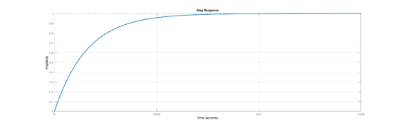
iv) When time = T = 1.6ms, we have Vout = 0.637 as shown below:

v) This can be done using the Bode plot of the system shown below:

The gain at w = 2*pi*50 rad/s is -1dB (0.9) approx and phase at around -28 degrees.
Thus, the output is y(t) = 0.9 sin(2*pi*50*t)
*******************************************************************
PS: Please do not forget the thumbs up!!
Add Answer to:
1) Design a low-pass RC device with the following
specifications:
a) Input x(t) and output y(t)...
Design a second-order Butterworth low-pass filter to satisfy the specifications a. The dc gain is...
 Design a second-order Butterworth low-pass filter to satisfy the specifications a. The dc gain is unity (zero dB); b. The gain is no smaller than -1 dB for frequencies between 0 and 2,000 Hz; and c. The gain is no larger than -40 dB for frequencies larger than 40 kHz. Determine a circuit realization as a series RLC low-pass filter. Pick reasonable values of R, L, and C.
Design a second-order Butterworth low-pass filter to satisfy the specifications a. The...
Design a second-order Butterworth low-pass filter to satisfy the specifications a. The dc gain is unity (zero dB); b. The gain is no smaller than -1 dB for frequencies between 0 and 2,000 Hz; and c. The gain is no larger than -40 dB for frequencies larger than 40 kHz. Determine a circuit realization as a series RLC low-pass filter. Pick reasonable values of R, L, and C.
Design a second-order Butterworth low-pass filter to satisfy the specifications a. The...
If g(t) and y(t) are the input and the output, respectively, of a simple RC low-pass filter (Fig....
 If g(t) and y(t) are the input and the output, respectively, of a simple RC low-pass filter (Fig. 3.27a), determine the transfer function H() and sketch H(, 0h(), and td(). For distortionless transmission through this filter, what is the requirement on the bandwidth of g(t) if amplitude response variation within 2% and time delay variation within 5% are tolerable? What is the transmission delay? Find the output y(t) g(t)
If g(t) and y(t) are the input and the output, respectively,...
If g(t) and y(t) are the input and the output, respectively, of a simple RC low-pass filter (Fig. 3.27a), determine the transfer function H() and sketch H(, 0h(), and td(). For distortionless transmission through this filter, what is the requirement on the bandwidth of g(t) if amplitude response variation within 2% and time delay variation within 5% are tolerable? What is the transmission delay? Find the output y(t) g(t)
If g(t) and y(t) are the input and the output, respectively,...
Consider the low pass filter RC circuit where Ri+ E E(t) The rise time t, is...
 Consider the low pass filter RC circuit where Ri+ E E(t) The rise time t, is defined as the time required for a unit step response to go from 10% to 90% of its final value. Show that 0.35 3dB where f3dB-the 3dB bandwidth (in Hz) of the filter 2TTRC
1. Design a low-pass Chebyshev filter with the following specifications: (7pts) • Passband edge frequency of,...
 1. Design a low-pass Chebyshev filter with the following specifications: (7pts) • Passband edge frequency of, Wp = 2 rads' Passband ripple of 3dB Cut-off frequency is at mid-point of the transition band • Stopband attenuation of 20dB or greater beyond ws=2.5 rads! • Find the filter transfer function H(S)
Problem 1 A sinusodial signal x(t)- sin2t (t in seconds) is input to a system with frequency resp...
 Problem 1 A sinusodial signal x(t)- sin2t (t in seconds) is input to a system with frequency response: H(G What signal y(t) is observed at the output? Problem 2 The inverse Fourier transform of a system frequency response is given by h(t)t. The signal x(t) 3 cos(4t 0.5) is input to the system (t in seconds). (a) What is the expression of the signal y(t) at the system output? (b) What is the power attenuation in dB caused by the...
Using the windowing functions discussed in class, design a low-pass FIR filter with a cutoff freq...
 Using the windowing functions discussed in class, design a
low-pass FIR filter with a cutoff frequency of 2 kHz, a minimum
stop band attenuation of 40 dB, and a transition width of 200Hz.
The sampling frequency is 10kHz.
1. Using the windowing functions discussed in class, design a low-pass FIR filter with a cutoff frequency of 2 kHz, a minimum stop band attenuation of 40 dB, and a transition width of 200 Hz. The sampling frequency is 10 kHz 2....
Using the windowing functions discussed in class, design a
low-pass FIR filter with a cutoff frequency of 2 kHz, a minimum
stop band attenuation of 40 dB, and a transition width of 200Hz.
The sampling frequency is 10kHz.
1. Using the windowing functions discussed in class, design a low-pass FIR filter with a cutoff frequency of 2 kHz, a minimum stop band attenuation of 40 dB, and a transition width of 200 Hz. The sampling frequency is 10 kHz 2....
Design a first order high-pass Butterworth filter that achieves the following specifications: Cutoff frequency = 770...
Design a first order high-pass Butterworth filter that achieves the following specifications: Cutoff frequency = 770 Hz Stop-band corner frequency = 132 Hz dB slope = 20dB / decade Gain at 132 Hz ≈ -14.9 dB Show working for all determined values of R and C
1 10 10 10 0 1 (30) A. Design a low-pass fiter (op-amp based cascade design) that meets requirements: 1. Cutoff frequency: 16 KHz 2. Passband gain: 0 dB 3. Stopband gain:-60 dB/decade 4. All resi...
 1 10 10 10 0 1 (30) A. Design a low-pass fiter (op-amp based cascade design) that meets requirements: 1. Cutoff frequency: 16 KHz 2. Passband gain: 0 dB 3. Stopband gain:-60 dB/decade 4. All resistors must be 1.0 k2 or higher You have completed the design and implementation of the LP filter and are ready to deliver the filter for production. However, you are informed that the customer made a mistake and actually needed a stopband gain of-40 dB/decade...
A. Design a low-pass filter (op-amp based cascade design) that meets the following (30) requirements 1. Cutoff frequency: 3.4 KHz 2. Passband gain: 20 dB 3. Stopband gain: -40 dB/decade 4. All re...
 A. Design a low-pass filter (op-amp based cascade design) that meets the following (30) requirements 1. Cutoff frequency: 3.4 KHz 2. Passband gain: 20 dB 3. Stopband gain: -40 dB/decade 4. All resistors must be 1.0 k2 or higher. You have completed the design and implementation of the LP filter and are ready to deliver the filter for production. However, you are informed that the customer made a mistake and actually needed a stopb you have used in your design)....
A. Design a low-pass filter (op-amp based cascade design) that meets the following (30) requirements: 1. Cutoff frequency: 3.4 KHz Passband gain: 20 dB 2. 3. Stopband gain: -40 dB/decade 4. All re...
 A. Design a low-pass filter (op-amp based cascade design) that meets the following (30) requirements: 1. Cutoff frequency: 3.4 KHz Passband gain: 20 dB 2. 3. Stopband gain: -40 dB/decade 4. All resistors must be 1.0 kS2 or higher. You have completed the design and implementation of the LP filter and are ready to deliver the filter for production. However, you are informed that the customer made a mistake and actually needed a stopband gain of -60 dB/decade (not-40 dB/decade...
 Design a second-order Butterworth low-pass filter to satisfy the specifications a. The dc gain is unity (zero dB); b. The gain is no smaller than -1 dB for frequencies between 0 and 2,000 Hz; and c. The gain is no larger than -40 dB for frequencies larger than 40 kHz. Determine a circuit realization as a series RLC low-pass filter. Pick reasonable values of R, L, and C.
Design a second-order Butterworth low-pass filter to satisfy the specifications a. The...
Design a second-order Butterworth low-pass filter to satisfy the specifications a. The dc gain is unity (zero dB); b. The gain is no smaller than -1 dB for frequencies between 0 and 2,000 Hz; and c. The gain is no larger than -40 dB for frequencies larger than 40 kHz. Determine a circuit realization as a series RLC low-pass filter. Pick reasonable values of R, L, and C.
Design a second-order Butterworth low-pass filter to satisfy the specifications a. The...
 If g(t) and y(t) are the input and the output, respectively, of a simple RC low-pass filter (Fig. 3.27a), determine the transfer function H() and sketch H(, 0h(), and td(). For distortionless transmission through this filter, what is the requirement on the bandwidth of g(t) if amplitude response variation within 2% and time delay variation within 5% are tolerable? What is the transmission delay? Find the output y(t) g(t)
If g(t) and y(t) are the input and the output, respectively,...
If g(t) and y(t) are the input and the output, respectively, of a simple RC low-pass filter (Fig. 3.27a), determine the transfer function H() and sketch H(, 0h(), and td(). For distortionless transmission through this filter, what is the requirement on the bandwidth of g(t) if amplitude response variation within 2% and time delay variation within 5% are tolerable? What is the transmission delay? Find the output y(t) g(t)
If g(t) and y(t) are the input and the output, respectively,...
 Consider the low pass filter RC circuit where Ri+ E E(t) The rise time t, is defined as the time required for a unit step response to go from 10% to 90% of its final value. Show that 0.35 3dB where f3dB-the 3dB bandwidth (in Hz) of the filter 2TTRC
 1. Design a low-pass Chebyshev filter with the following specifications: (7pts) • Passband edge frequency of, Wp = 2 rads' Passband ripple of 3dB Cut-off frequency is at mid-point of the transition band • Stopband attenuation of 20dB or greater beyond ws=2.5 rads! • Find the filter transfer function H(S)
 Problem 1 A sinusodial signal x(t)- sin2t (t in seconds) is input to a system with frequency response: H(G What signal y(t) is observed at the output? Problem 2 The inverse Fourier transform of a system frequency response is given by h(t)t. The signal x(t) 3 cos(4t 0.5) is input to the system (t in seconds). (a) What is the expression of the signal y(t) at the system output? (b) What is the power attenuation in dB caused by the...
 Using the windowing functions discussed in class, design a
low-pass FIR filter with a cutoff frequency of 2 kHz, a minimum
stop band attenuation of 40 dB, and a transition width of 200Hz.
The sampling frequency is 10kHz.
1. Using the windowing functions discussed in class, design a low-pass FIR filter with a cutoff frequency of 2 kHz, a minimum stop band attenuation of 40 dB, and a transition width of 200 Hz. The sampling frequency is 10 kHz 2....
Using the windowing functions discussed in class, design a
low-pass FIR filter with a cutoff frequency of 2 kHz, a minimum
stop band attenuation of 40 dB, and a transition width of 200Hz.
The sampling frequency is 10kHz.
1. Using the windowing functions discussed in class, design a low-pass FIR filter with a cutoff frequency of 2 kHz, a minimum stop band attenuation of 40 dB, and a transition width of 200 Hz. The sampling frequency is 10 kHz 2....
 1 10 10 10 0 1 (30) A. Design a low-pass fiter (op-amp based cascade design) that meets requirements: 1. Cutoff frequency: 16 KHz 2. Passband gain: 0 dB 3. Stopband gain:-60 dB/decade 4. All resistors must be 1.0 k2 or higher You have completed the design and implementation of the LP filter and are ready to deliver the filter for production. However, you are informed that the customer made a mistake and actually needed a stopband gain of-40 dB/decade...
 A. Design a low-pass filter (op-amp based cascade design) that meets the following (30) requirements 1. Cutoff frequency: 3.4 KHz 2. Passband gain: 20 dB 3. Stopband gain: -40 dB/decade 4. All resistors must be 1.0 k2 or higher. You have completed the design and implementation of the LP filter and are ready to deliver the filter for production. However, you are informed that the customer made a mistake and actually needed a stopb you have used in your design)....
 A. Design a low-pass filter (op-amp based cascade design) that meets the following (30) requirements: 1. Cutoff frequency: 3.4 KHz Passband gain: 20 dB 2. 3. Stopband gain: -40 dB/decade 4. All resistors must be 1.0 kS2 or higher. You have completed the design and implementation of the LP filter and are ready to deliver the filter for production. However, you are informed that the customer made a mistake and actually needed a stopband gain of -60 dB/decade (not-40 dB/decade...
Most questions answered within 3 hours.
-
(CO 2) A field can be added to a report to
values for two or more...
asked 15 minutes ago -
Identify 3 research scenarios that might provide a low,
medium, and high degree of variability in...
asked 38 minutes ago -
how
does gravity affect the trajectory of projectile? what would be the
shape of the trajactory...
asked 1 hour ago -
Two small plastic spheres are given positive electrical charges.
When they are a distance of 15.4...
asked 1 hour ago -
An acidic solution containing gold ions is
electrolyzed, producing gaseous oxygen (from water) at the anode...
asked 1 hour ago -
Assume that the population of Mexico is 128
million and that the population increases 1.01
percentannually....
asked 2 hours ago -
Can someone please help me add appropriate descriptive
comments to each line of code in the...
asked 2 hours ago -
Romeo wishes to throw a bouquet of flowers to Juliet, who is on
a second-story balcony,...
asked 3 hours ago -
Why is QE a controversial monetary policy tool.
A. It may lead to excessive inflation.B. By...
asked 4 hours ago -
Principles of Programming midterm study guide help!
1.)
______ Which of the following would reference the...
asked 3 hours ago -
A finite potential well has depth U0 = 2.78 eV . What is the
penetration distance...
asked 4 hours ago -
1. The bus bars of a power station are in two sections A and B
separated...
asked 4 hours ago