For the DC circuit shown here, Kirchhoff’s Rules and Ohm’s Law tell us the following relationships...
For the DC circuit shown here, Kirchhoff’s Rules and Ohm’s Law
tell us
the following relationships between the currents I1, I2, I3, I4,
the resistances R1, R2, R3,
and the voltage V provided by the battery:
I2+ I3=I1
I2+ I3=I4
I1R1+ I3R3=V
I1R1+ I2R2=V
Write a function find_current.m which takes as inputs the values
for V , R1, R2, and R3,
and returns as output a column vector containing the values of the
currents I1, I2, I3, I4,
in that order.
Suppose R1= 100 Ohms, R2= 200 Ohms, and V = 9 Volts. Plot I2,
I3,
and I2+I3versus R3using the values R3= 0.1, 0.2, 0.3, · · · , 10000
Ohms, in two different
ways.
First, in figure(1), plot this using linear axes; this is what you
get from the plot
command. All three quantities I2, I3, and I2+ I3should be shown in
this one figure.
Second, in figure(2), plot this with a linear vertical axis and a
logarithmic horizontal
axis; this is what you get from the semilogx command, which uses
the same syntax as
the plot command. Again, all three quantities I2, I3, and I2+
I3should be shown in this
one figure.
Your figures must have labelled axes (including units), and use the
legend command to
specify which curve is which.
Please submit the files find_current.m and
plot_current.m.
Homework Answers
Program Screen Shot:

Sample Output:


Program Code to Copy:
%
%
function I = find_current(V,R1,R2,R3)
% express the equations in form Ax = b
%% A
A = [
-1 1 1 0;
0 1 1 -1;
R1 0 R3 0;
R1 R2 0 0
];
%
%% b
b = [
0;
0;
V;
V
];
%
%% solving for I
I = A\b;
end
__________________________________________
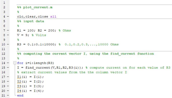
%% plot_current.m
%
clc,clear,close all
%% input data
%
R1 = 100; R2 = 200; % Ohms
V = 9; % Volts
%
R3 = 0.1:0.1:10000; % 0.1,0.2,0.3,...,10000 Ohms
%
%% computing the current vector I, using the find_current
function
%
for i=1:length(R3)
I = find_current(V,R1,R2,R3(i)); % compute current on for each
value of R3
% extract current values from the the column vector I
I1(i) = I(1);
I2(i) = I(2);
I3(i) = I(3);
I4(i) = I(4);
end
%
%% plotting
%
figure,plot(R3,I2,'- b',R3,I3,'- g',R3,I2+I3,'- r')
legend('I_2','I_3','I_2+I_3'),grid on,grid minor
xlabel('R_3 [Ohms]'),ylabel('Current [Amperes]')
%
%% plot with logarithm
%
figure,semilogx(R3,I2,'- b',R3,I3,'- g',R3,I2+I3,'- r')
legend('I_2','I_3','I_2+I_3'),grid on,grid minor
xlabel('R_3 [Ohms]'),ylabel('Current [Amperes]')
------------------------------------------------------------------------------
COMMENT DOWN FOR ANY QUERY RELATED TO THIS ANSWER,
IF YOU'RE SATISFIED, GIVE A THUMBS UP
~yc~
Add Answer to:
For the DC circuit shown here, Kirchhoff’s Rules and Ohm’s Law
tell us
the following relationships...
Consider the electrical circuit shown above. It consists of two identical ideal batteries, V1 = V2...
 Consider the electrical
circuit shown above. It consists of two identical ideal batteries,
V1 = V2 = 24 V, and five resistors.
1)
Which of the following equations is not valid?
I2= I1 + I3
I2R2 + I3R3 +
V2 = 0
I1R1 + I2R2 -
V1 = 0
2)
Suppose the resistor R3 is shorted out, so that it
acts like a wire. What can we say about the current labelled
I1?
I1 is positive.
I1 is negative.
I1...
Consider the electrical
circuit shown above. It consists of two identical ideal batteries,
V1 = V2 = 24 V, and five resistors.
1)
Which of the following equations is not valid?
I2= I1 + I3
I2R2 + I3R3 +
V2 = 0
I1R1 + I2R2 -
V1 = 0
2)
Suppose the resistor R3 is shorted out, so that it
acts like a wire. What can we say about the current labelled
I1?
I1 is positive.
I1 is negative.
I1...
Hi I need help with answers 11-15. thank you The next three questions are about this...
 Hi I need help with answers 11-15. thank you
The next three questions are about this circuit. The voltage of
the battery is 12 V, and the values of the resistances are:
R1 = 5 ohms, R2 = 10 ohms, R3 = 15
ohms, and R4 = 20 ohms.
The next three questions pertain to the following situation.
11) R1 and R4
are in:
parallel
series
neither
12) Compare the magnitude of the
voltage across R2 and R4
V2 > V4
V2...
Hi I need help with answers 11-15. thank you
The next three questions are about this circuit. The voltage of
the battery is 12 V, and the values of the resistances are:
R1 = 5 ohms, R2 = 10 ohms, R3 = 15
ohms, and R4 = 20 ohms.
The next three questions pertain to the following situation.
11) R1 and R4
are in:
parallel
series
neither
12) Compare the magnitude of the
voltage across R2 and R4
V2 > V4
V2...
Assume the resistance values are R1 = 2,200 Ohm, R2 = 1,300 Ohm, R3 = 4,200...
 Assume the resistance values are R1 = 2,200 Ohm, R2 = 1,300 Ohm, R3 = 4,200 Ohm, and R4 = 5,900 Ohm, and the battery emfs are epsilon1 = 1.5 V and Epsilon2 = 3.0 V. Use Kirchhoff?s rules to analyze the circuit in the figure below. (a) Let I1 be the branch current though R1, I2 be the branch current through R2, and I3 be the branch current through R3. Write Kirchhoff?s loop rule relation for a loop that...
Consider the circuit shown in the figure(Figure 1). Suppose thefour resistors in this circuit have...
 Consider the circuit shown in the figure(Figure 1). Suppose the
four resistors in this circuit have the values R1 = 13 Ω , R2 = 7.2
Ω , R3 = 6.2 Ω , and R4= 13 Ω , and that the emf of the battery is
E = 18 V .Part AFind the current through each resistor using the rules for
series and parallel resistors. Express your answers using two
significant figures separated by commas.I1,I2,I3,I4=______APart BFind the current through each...
Consider the circuit shown in the figure(Figure 1). Suppose the
four resistors in this circuit have the values R1 = 13 Ω , R2 = 7.2
Ω , R3 = 6.2 Ω , and R4= 13 Ω , and that the emf of the battery is
E = 18 V .Part AFind the current through each resistor using the rules for
series and parallel resistors. Express your answers using two
significant figures separated by commas.I1,I2,I3,I4=______APart BFind the current through each...
In the circuit shown in the figure. R1 = 15,00 Ohm, R2 = 10.0 Ohm, R3...
 In the circuit shown in the figure. R1 = 15,00 Ohm, R2 = 10.0 Ohm, R3 = 5.0 Ohm, V emf,1 = 15.0 V. and Vemf,2 = 10.0 V. Using Kirchhoff's Loop and Junction Rules, determine the currents i1, i2, and i3 flowing through R1, R2, and R3, respectively, in the direction indicated in the figure.
For the multi-loop circuit shown, which of the following equations correctly describes the circuit? (Give ALL...
 For the multi-loop circuit shown, which of the following
equations correctly describes the circuit? (Give ALL CORRECT
answers, eg. B, AC, BCD ...)
A) i1 = i3 + i2
B) i1 + i3 = i2
C) ε2 - ε3 = i2 R2 +
i3 R3
D) ε3 - ε1 = i3 R3 -
i1 R1
E) ε1 + ε2 = i1 R1 -
i2 R2
F) ε1 + ε2 = i1 R1 +
i2 R2
G) ε2 + ε3 =...
For the multi-loop circuit shown, which of the following
equations correctly describes the circuit? (Give ALL CORRECT
answers, eg. B, AC, BCD ...)
A) i1 = i3 + i2
B) i1 + i3 = i2
C) ε2 - ε3 = i2 R2 +
i3 R3
D) ε3 - ε1 = i3 R3 -
i1 R1
E) ε1 + ε2 = i1 R1 -
i2 R2
F) ε1 + ε2 = i1 R1 +
i2 R2
G) ε2 + ε3 =...
1. For the circuit shown, the following is known: R1 = 82, R3 = 1.2, v2...
 1. For the circuit shown, the following is known: R1 = 82, R3 = 1.2, v2 = -10 V, and i3 = 2 A. Determine the unknown voltages and currents (V1, V3, i1, and i2) as well as R2. R2 02 12 V iztiz R3 a 03 R1 U 1 10 V +
Using Kirchhoff's rules, find thecurrents I1, I2, and I3 in the circuit shown where R1...
 Using Kirchhoff's rules, find the
currents I1, I2, and I3 in the circuit shown where R1 = 1.2 Ω, R2 =
2.8 Ω, and R3 = 6.3 Ω.
Using Kirchhoff's rules, find the
currents I1, I2, and I3 in the circuit shown where R1 = 1.2 Ω, R2 =
2.8 Ω, and R3 = 6.3 Ω.
In the circuit shown in the figure below, determine the current in each resistor at the following times. Use r1, r2, an...
 In the circuit shown in the figure below, determine the current
in each resistor at the following times. Use r1, r2, and r3 for
R1, R2, and
R3, respectively, and use E for .
(a) at the moment the switch is closed
I1 =
I2 =
I3 =
(b) a long time after the switch is closed
I1 =
I2 =
I3 =
After the switch has been closed a long time, and reopened,
determine each current at the following...
In the circuit shown in the figure below, determine the current
in each resistor at the following times. Use r1, r2, and r3 for
R1, R2, and
R3, respectively, and use E for .
(a) at the moment the switch is closed
I1 =
I2 =
I3 =
(b) a long time after the switch is closed
I1 =
I2 =
I3 =
After the switch has been closed a long time, and reopened,
determine each current at the following...
From the circuit shown below, (a) use KCL and KVL to solve for the three currents....
 From the circuit shown below,
(a) use KCL and KVL to solve for the three currents.
(b) With the given data below and the two currents flowing
clockwise, determine both currents using mesh analysis and the
voltages across each resistor.
r1= 3 Ohms
r2= 7 Ohms
r3= 2 Ohms
r4= 8 Ohms
a M 10 V 30 il 222 i2 722 892 i3 12 V W
From the circuit shown below,
(a) use KCL and KVL to solve for the three currents.
(b) With the given data below and the two currents flowing
clockwise, determine both currents using mesh analysis and the
voltages across each resistor.
r1= 3 Ohms
r2= 7 Ohms
r3= 2 Ohms
r4= 8 Ohms
a M 10 V 30 il 222 i2 722 892 i3 12 V W
 Consider the electrical
circuit shown above. It consists of two identical ideal batteries,
V1 = V2 = 24 V, and five resistors.
1)
Which of the following equations is not valid?
I2= I1 + I3
I2R2 + I3R3 +
V2 = 0
I1R1 + I2R2 -
V1 = 0
2)
Suppose the resistor R3 is shorted out, so that it
acts like a wire. What can we say about the current labelled
I1?
I1 is positive.
I1 is negative.
I1...
Consider the electrical
circuit shown above. It consists of two identical ideal batteries,
V1 = V2 = 24 V, and five resistors.
1)
Which of the following equations is not valid?
I2= I1 + I3
I2R2 + I3R3 +
V2 = 0
I1R1 + I2R2 -
V1 = 0
2)
Suppose the resistor R3 is shorted out, so that it
acts like a wire. What can we say about the current labelled
I1?
I1 is positive.
I1 is negative.
I1...
 Hi I need help with answers 11-15. thank you
The next three questions are about this circuit. The voltage of
the battery is 12 V, and the values of the resistances are:
R1 = 5 ohms, R2 = 10 ohms, R3 = 15
ohms, and R4 = 20 ohms.
The next three questions pertain to the following situation.
11) R1 and R4
are in:
parallel
series
neither
12) Compare the magnitude of the
voltage across R2 and R4
V2 > V4
V2...
Hi I need help with answers 11-15. thank you
The next three questions are about this circuit. The voltage of
the battery is 12 V, and the values of the resistances are:
R1 = 5 ohms, R2 = 10 ohms, R3 = 15
ohms, and R4 = 20 ohms.
The next three questions pertain to the following situation.
11) R1 and R4
are in:
parallel
series
neither
12) Compare the magnitude of the
voltage across R2 and R4
V2 > V4
V2...
 Assume the resistance values are R1 = 2,200 Ohm, R2 = 1,300 Ohm, R3 = 4,200 Ohm, and R4 = 5,900 Ohm, and the battery emfs are epsilon1 = 1.5 V and Epsilon2 = 3.0 V. Use Kirchhoff?s rules to analyze the circuit in the figure below. (a) Let I1 be the branch current though R1, I2 be the branch current through R2, and I3 be the branch current through R3. Write Kirchhoff?s loop rule relation for a loop that...
 Consider the circuit shown in the figure(Figure 1). Suppose the
four resistors in this circuit have the values R1 = 13 Ω , R2 = 7.2
Ω , R3 = 6.2 Ω , and R4= 13 Ω , and that the emf of the battery is
E = 18 V .Part AFind the current through each resistor using the rules for
series and parallel resistors. Express your answers using two
significant figures separated by commas.I1,I2,I3,I4=______APart BFind the current through each...
Consider the circuit shown in the figure(Figure 1). Suppose the
four resistors in this circuit have the values R1 = 13 Ω , R2 = 7.2
Ω , R3 = 6.2 Ω , and R4= 13 Ω , and that the emf of the battery is
E = 18 V .Part AFind the current through each resistor using the rules for
series and parallel resistors. Express your answers using two
significant figures separated by commas.I1,I2,I3,I4=______APart BFind the current through each...
 In the circuit shown in the figure. R1 = 15,00 Ohm, R2 = 10.0 Ohm, R3 = 5.0 Ohm, V emf,1 = 15.0 V. and Vemf,2 = 10.0 V. Using Kirchhoff's Loop and Junction Rules, determine the currents i1, i2, and i3 flowing through R1, R2, and R3, respectively, in the direction indicated in the figure.
 For the multi-loop circuit shown, which of the following
equations correctly describes the circuit? (Give ALL CORRECT
answers, eg. B, AC, BCD ...)
A) i1 = i3 + i2
B) i1 + i3 = i2
C) ε2 - ε3 = i2 R2 +
i3 R3
D) ε3 - ε1 = i3 R3 -
i1 R1
E) ε1 + ε2 = i1 R1 -
i2 R2
F) ε1 + ε2 = i1 R1 +
i2 R2
G) ε2 + ε3 =...
For the multi-loop circuit shown, which of the following
equations correctly describes the circuit? (Give ALL CORRECT
answers, eg. B, AC, BCD ...)
A) i1 = i3 + i2
B) i1 + i3 = i2
C) ε2 - ε3 = i2 R2 +
i3 R3
D) ε3 - ε1 = i3 R3 -
i1 R1
E) ε1 + ε2 = i1 R1 -
i2 R2
F) ε1 + ε2 = i1 R1 +
i2 R2
G) ε2 + ε3 =...
 1. For the circuit shown, the following is known: R1 = 82, R3 = 1.2, v2 = -10 V, and i3 = 2 A. Determine the unknown voltages and currents (V1, V3, i1, and i2) as well as R2. R2 02 12 V iztiz R3 a 03 R1 U 1 10 V +
 Using Kirchhoff's rules, find the
currents I1, I2, and I3 in the circuit shown where R1 = 1.2 Ω, R2 =
2.8 Ω, and R3 = 6.3 Ω.
Using Kirchhoff's rules, find the
currents I1, I2, and I3 in the circuit shown where R1 = 1.2 Ω, R2 =
2.8 Ω, and R3 = 6.3 Ω.
 In the circuit shown in the figure below, determine the current
in each resistor at the following times. Use r1, r2, and r3 for
R1, R2, and
R3, respectively, and use E for .
(a) at the moment the switch is closed
I1 =
I2 =
I3 =
(b) a long time after the switch is closed
I1 =
I2 =
I3 =
After the switch has been closed a long time, and reopened,
determine each current at the following...
In the circuit shown in the figure below, determine the current
in each resistor at the following times. Use r1, r2, and r3 for
R1, R2, and
R3, respectively, and use E for .
(a) at the moment the switch is closed
I1 =
I2 =
I3 =
(b) a long time after the switch is closed
I1 =
I2 =
I3 =
After the switch has been closed a long time, and reopened,
determine each current at the following...
 From the circuit shown below,
(a) use KCL and KVL to solve for the three currents.
(b) With the given data below and the two currents flowing
clockwise, determine both currents using mesh analysis and the
voltages across each resistor.
r1= 3 Ohms
r2= 7 Ohms
r3= 2 Ohms
r4= 8 Ohms
a M 10 V 30 il 222 i2 722 892 i3 12 V W
From the circuit shown below,
(a) use KCL and KVL to solve for the three currents.
(b) With the given data below and the two currents flowing
clockwise, determine both currents using mesh analysis and the
voltages across each resistor.
r1= 3 Ohms
r2= 7 Ohms
r3= 2 Ohms
r4= 8 Ohms
a M 10 V 30 il 222 i2 722 892 i3 12 V W
Most questions answered within 3 hours.
-
Using the 12th edition of Language Awareness,
complete the following assignment:
After reading Akiba Solomon's "Thugs....
asked 6 minutes ago -
For all problems assume an effective monthly interest rate of 1%
unless otherwise indicated in the...
asked 16 minutes ago -
Fix all syntax and logical errors for the following program.
Please generate the correct output. //...
asked 25 minutes ago -
The USPS sells money orders identified by an 11 –digit number
x1, x2, …, x11. The...
asked 28 minutes ago -
Provide an example of equilibrium in relation to
Newton’s First and Second Laws. Explain your answer....
asked 29 minutes ago -
You are __________ to commit a Type I error using the 0.05 level
of significance than...
asked 48 minutes ago -
1. the following results are obtained:
200
kiwi
575 wild-type
What can we conclude about the...
asked 52 minutes ago -
Explain how you might use E. coli bacteria to produce human
growth hormone using the following:...
asked 53 minutes ago -
WHAT IS THE EFFEKT OF ADD K2CO3 TO ( METHANOL OG WATER)?
asked 1 hour ago -
Calculate the cell potential, the equilibrium constant, and the
free-energy change for: Ca(s)+Mn2+(aq)(1M)⇌Ca2+(aq)(1M)+Mn(s) given
the following...
asked 1 hour ago -
Determine the pH at the equivalence (stoichiometric) point in
the titration of 48 mL of 0.28...
asked 1 hour ago -
11. In CPM/PERT, an activity that is on the critical path
A. has equal values for...
asked 1 hour ago