
Homework Answers

Add Answer to:
The figure shows a rectangular member OB, made from ¼-in-thick aluminum plate, pinned to the grou...
The figure shows a rectangular member OB, made from 1⁄4-in-thick aluminum plate, pinned to the gr...
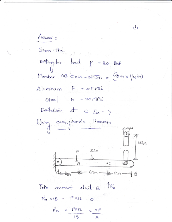
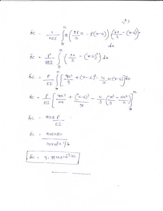
 The figure shows a rectangular member OB, made from 1⁄4-in-thick
aluminum plate, pinned to the ground at one end and supported by a
1/3-in-diameter round steel rod with hooks formed on the ends. A
load of 80 lbf is applied as shown. Use Castigliano’s Theorem to
determine the vertical deflection at point C, midway between points
A and B. Aluminum: E = 10 Mpsi, Steel: E = 30 Mpsi.
v
The figure shows a rectangular member OB, made from ¼-in-thick...
The figure shows a rectangular member OB, made from 1⁄4-in-thick
aluminum plate, pinned to the ground at one end and supported by a
1/3-in-diameter round steel rod with hooks formed on the ends. A
load of 80 lbf is applied as shown. Use Castigliano’s Theorem to
determine the vertical deflection at point C, midway between points
A and B. Aluminum: E = 10 Mpsi, Steel: E = 30 Mpsi.
v
The figure shows a rectangular member OB, made from ¼-in-thick...
Problem 3. An aluminum beam is shown in the figure with a rectangular cross section. The...
 Problem 3. An aluminum beam is shown in the figure with a rectangular cross section. The beam is pinned to the ground at one end and supported by a round steel rod with hooks formed on the ends. Use Castigliano's method to find deflection at point B. T 100 lbf 7-in dia. 12 in 2 in 1-in thick B . 04_P0-—. 7 in 12 in — 6 in
-in dia.. 95 lbf 16 in 2 in -in thick -A 5 in 18 in The...
 -in dia.. 95 lbf 16 in 2 in -in thick -A 5 in 18 in The figure shows a rectangular member o B, made from 4-in-thick aluminum plate, pinned to the ground at one end and supported by a-in-diameter round steel rod with hooks formed on the ends. A load of 95 lbf is applied as shown. Use superposition to
Need help, can you show all steps! Much appreciated! 80 lbf -in dia 13 in -in...
 Need help, can you show all steps! Much appreciated!
80 lbf -in dia 13 in -in thick 2 in 24 in 32 in 8 in The figure shows a rectangular member OB, made from -in-thick aluminum plate, pinned to the ground at one end and supported by in-diameter round steel rod with hooks formed on the ends. A load of 80 Ibi is applied as shown. Use superposition to determine the vertical deflection at pointB 0.031219 in
Need help, can you show all steps! Much appreciated!
80 lbf -in dia 13 in -in thick 2 in 24 in 32 in 8 in The figure shows a rectangular member OB, made from -in-thick aluminum plate, pinned to the ground at one end and supported by in-diameter round steel rod with hooks formed on the ends. A load of 80 Ibi is applied as shown. Use superposition to determine the vertical deflection at pointB 0.031219 in
1. For the state of stress depicted in Fig. 1, calculate the principle stresses and 02...
 1. For the state of stress depicted in Fig. 1, calculate the principle stresses and 02 and associated principle directions Opı and Op2, and compute the von Mises stress OVM. Assume plane-stress conditions. 30 kpsi HII → 20 kpsi 1.......> 18 kpsi Fig. 1 2. For the beam depicted in Fig. 2, determine the deflection and slope of the beam at end C (y and dy/dx[.), as well as the deflection at x =12 in. The beam is made of...
Question 1 The stepped flat bar has a constant thickness of 8.0 mm. It carries three concentrated loads as shown...
 Question 1 The stepped flat bar has a constant thickness of 8.0 mm. It carries three concentrated loads as shown. Let P 200 N, L 180 mm, L, = 80 mm, and Ls 40 mm. Compute the maximum stress due to bending and state where it occurs. Note: The bar is braced against lateral bending and twisting. 100 mm 140 mm 1CX) mm 140 mm 2P Flat plate r3 mm t8 mm typical 12 m 24 mm-36 mm 48 mm...
 The figure shows a rectangular member OB, made from 1⁄4-in-thick
aluminum plate, pinned to the ground at one end and supported by a
1/3-in-diameter round steel rod with hooks formed on the ends. A
load of 80 lbf is applied as shown. Use Castigliano’s Theorem to
determine the vertical deflection at point C, midway between points
A and B. Aluminum: E = 10 Mpsi, Steel: E = 30 Mpsi.
v
The figure shows a rectangular member OB, made from ¼-in-thick...
The figure shows a rectangular member OB, made from 1⁄4-in-thick
aluminum plate, pinned to the ground at one end and supported by a
1/3-in-diameter round steel rod with hooks formed on the ends. A
load of 80 lbf is applied as shown. Use Castigliano’s Theorem to
determine the vertical deflection at point C, midway between points
A and B. Aluminum: E = 10 Mpsi, Steel: E = 30 Mpsi.
v
The figure shows a rectangular member OB, made from ¼-in-thick...
 Problem 3. An aluminum beam is shown in the figure with a rectangular cross section. The beam is pinned to the ground at one end and supported by a round steel rod with hooks formed on the ends. Use Castigliano's method to find deflection at point B. T 100 lbf 7-in dia. 12 in 2 in 1-in thick B . 04_P0-—. 7 in 12 in — 6 in
 -in dia.. 95 lbf 16 in 2 in -in thick -A 5 in 18 in The figure shows a rectangular member o B, made from 4-in-thick aluminum plate, pinned to the ground at one end and supported by a-in-diameter round steel rod with hooks formed on the ends. A load of 95 lbf is applied as shown. Use superposition to
 Need help, can you show all steps! Much appreciated!
80 lbf -in dia 13 in -in thick 2 in 24 in 32 in 8 in The figure shows a rectangular member OB, made from -in-thick aluminum plate, pinned to the ground at one end and supported by in-diameter round steel rod with hooks formed on the ends. A load of 80 Ibi is applied as shown. Use superposition to determine the vertical deflection at pointB 0.031219 in
Need help, can you show all steps! Much appreciated!
80 lbf -in dia 13 in -in thick 2 in 24 in 32 in 8 in The figure shows a rectangular member OB, made from -in-thick aluminum plate, pinned to the ground at one end and supported by in-diameter round steel rod with hooks formed on the ends. A load of 80 Ibi is applied as shown. Use superposition to determine the vertical deflection at pointB 0.031219 in
 1. For the state of stress depicted in Fig. 1, calculate the principle stresses and 02 and associated principle directions Opı and Op2, and compute the von Mises stress OVM. Assume plane-stress conditions. 30 kpsi HII → 20 kpsi 1.......> 18 kpsi Fig. 1 2. For the beam depicted in Fig. 2, determine the deflection and slope of the beam at end C (y and dy/dx[.), as well as the deflection at x =12 in. The beam is made of...
 Question 1 The stepped flat bar has a constant thickness of 8.0 mm. It carries three concentrated loads as shown. Let P 200 N, L 180 mm, L, = 80 mm, and Ls 40 mm. Compute the maximum stress due to bending and state where it occurs. Note: The bar is braced against lateral bending and twisting. 100 mm 140 mm 1CX) mm 140 mm 2P Flat plate r3 mm t8 mm typical 12 m 24 mm-36 mm 48 mm...
Most questions answered within 3 hours.
-
Kylie is a single mom with two dependent children,
Tanner, age 7 and Olivia, age 11....
asked 23 minutes ago -
Phosphorous + bromine = phosphorous tribromide. If 35.0 g of
bromine are reacted and 27.9 grams...
asked 1 hour ago -
Derive the long wavelength limit of the Planck energy density
distribution
asked 1 hour ago -
Calculate the pH of each of the following solutions.
0.50 M HBr
3.1×10⁻⁴ M KOH
4.2×10⁻⁵...
asked 5 hours ago -
For the year ended December 31, Depot Max’s cost of merchandise
sold was $85,600. Inventory at the...
asked 5 hours ago -
Week 10 - Professional Memo Assignment
Professional Memo Assignment
Your mission for this week, should you...
asked 5 hours ago -
Write a Python program that stores the data for each
player on the team, and it...
asked 5 hours ago -
In
the last 3 months, mike never knows when he is going to get his
allowance...
asked 5 hours ago -
Is Ca(OH)2 a Bronsted base, Lewis base, or both? Why?
asked 5 hours ago -
1A- Why don’t voters complain about U.S. tariffs on imported
sugar?
Because sugar is only a...
asked 5 hours ago -
Cash Payback Period
Primera Banco is evaluating two capital investment proposals for
a drive-up ATM kiosk,...
asked 5 hours ago -
Create a button in Swift (Xcode) that will create a charge,
create a charge using Stripe's...
asked 5 hours ago