


Measurement of the horizontal component of Earth's magnetic field induction by tangensgalvanometer In each point the Earth's magnetic field is directed in any defined angle with respect to the horizontal plane and meridian, therefore the induction vector of Earth's magnetic field usually is splitted into two components: horizontal and vertical one. The magnetic arrow with vertical axis then will oriented by horizontal component of magnetic field. This property is used in devices called tangensgalvenometres (TG). By TG is possible to define either the horizontal component of Earth magnetic field Bo, or to measure current, if the value of this is known at any specific place. For Riga Bo= 0.168 x10⁻⁴ T TG consists of vertically placed loop with one or more tums of wire (1 on fig.1). In the center of this loop the magnetic arrow (2 on fig.1) or compass is placed which is able to turn around the vertical axis in horizontal plane. If there is no current in TG, than arrow is positioned along the meridian of the Earth magnetic field. The loops of wire should be oriented also in this direction. If the current flows through the wire, the induction vector Bi of generated Figl.Te magnetic field is perpendicular both to the wire plane and Earth's tangensgalvanometer The schematic view of the magnetic field vector Bo Vectors of discussed fields are shown on fig.2 (top view). Bre Under the action of these two fields magnetic arrow will be oriented along the resultant field Bre and is deflected on angle ф from the original direction. The value of this angle can be derived from following equation (see Fig.2): The plane of windings Fig.2. The scheme of Earth's and current magnetic fields inside TG (top view)
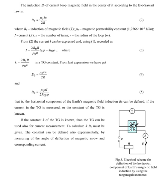
The induction B of current loop magnetic field in the center of it according to the Bio-Sawart law is: 2R where B- induction of magnetic field (T); - magnetic permeability constant (1,2566x10⁶ H/m); I- current (A); the number of turns; r-the radius of the loop (m). From (2) the current I can be expressed and, using (1), recorded as ton 2Bo R Om 20A s a TG constant. From last expression we have got 0 2R and 2Rig that is, the horizontal component of the Earth's magnetic field induction Bo can be defined, if the current in the TG is measured, or the constant of the TG is known. If the constant k of the TG is known, than the TG can be used also for current measurement. To calculate k Bo must be given. The constant can be defined also experimentally, by measuring of the angle of deflection of magnetic arrow and corresponding current Fig.3. Electrical scheme for definition of the horizontal component of Earth's magnetic field induction by using the tangensgalvanometer
Laboratorijas darbs 2.5 The scheme of used circuit is shown on Fig.3. Before the beginning of measurement the loop of wire should be placed parallel to the meridian of Earth's magnetic field. The magnetic arrow should be placed very precisely in the center of the TG. The current in the loop is measured by ammeter A The six-pole switch S is used to change the direction of the current on the opposite one. For precise definition of the angle φ, current of both directions is used and corresponding angles of deflection are defined (ф 1 and ф 2). The mean value of ф should be taken for calculations: 91 + 92 Measurements should be performed by different currents, which can be changed by variable resistor R, and Bo should be calculated by using (5) The readings of the TG can be disturbed by neighbourhood magnetic field, therefore it should be placed as far as possible from other parts of the circuit (resistor, source of current), connecting wires and ferromagnetic objects Possible appointments for the work. . To determine the horizontal component of the Earth's magnetic field induction at specific place. 2. To construct the graph tgp fl) and define the constant of the tangensgalvanometer.
Homework Answers
The tangent galvanometer was used to find out the horizontal intensity of the earth's magnetic field.Using the tangent galvanometer experiment,Bav was found to be 1.69*10^(-5) while the given value is B0=1.68*10^(-5) which shows only a very small error value(error=.005%).The galvanometer constant was also found out by plotting a graph between tan phi and I which happens to be a straight line.
Add Answer to:
This is my experiment about Earth magnetic field induction by tangensgalvonometer. I must additio...
I need answer for these questions Record the ammeter current. Reverse the current (and the ammeter)...
 I need answer for these questions
Record the ammeter current. Reverse the current (and the ammeter) and adjust the resist deflects exactly 45 degree on the opposite side of the magnetic meridian. Record the current currents and calculate, using the theoretical formula for the magnetic field at the center horizontal component of the earth's magnetic field. Determination of the vertical component of the earth's magnetic field and the total. Set the dipping needle's plane along the magnetic meridian and measure...
I need answer for these questions
Record the ammeter current. Reverse the current (and the ammeter) and adjust the resist deflects exactly 45 degree on the opposite side of the magnetic meridian. Record the current currents and calculate, using the theoretical formula for the magnetic field at the center horizontal component of the earth's magnetic field. Determination of the vertical component of the earth's magnetic field and the total. Set the dipping needle's plane along the magnetic meridian and measure...
A circular wire loop of radius 1.13 m is placed in a magnetic field of magnitude...
A circular wire loop of radius 1.13 m is placed in a magnetic field of magnitude 0.495 T. The normal to the plane of the loop makes an angle of 30.0° with the magnetic field (see figure a). The current in the loop is 1.95 A in the direction shown. a)Find the magnetic moment of the loop and the magnitude of the torque at this instant
(S)A 20.0cm diameter circular loop of wire is placed in a 10T magnetic field with its...
 (S)A 20.0cm diameter circular loop of wire is placed in a 10T magnetic field with its plane perpendicular to the magnetic field. The field is applied outward. In 0.40s the loop is rotated until the perpendicular to the loop makes an angle of 30 0 with the field lines (20 credits) Calculate the magnetic flux through the loop when its plane is perpendicular to magnetic field. (a) Calculate the magnetic flux through the loop when its plane makes an angle...
A square coil of wire of side 3.80 cm is placed in a uniform magnetic field...
 A square coil of wire of side 3.80 cm is placed in a uniform magnetic field of magnitude 2.00 T directed into the page as in the figure shown below. The coil has 30.5 turns and a resistance of 0.780 2. If the coil is rotated through an angle of 90.00 about the horizontal axis shown in 0.335 s, find the following. Rotation axis X X X (a) the magnitude of the average emf induced in the coil during this...
nt to p in the loop? (b) If the magnetic field r of 2.1 T, what...
 nt to p in the loop? (b) If the magnetic field r of 2.1 T, what is the magnitude of the ra verage emf has the 24. A uniform magnetic field is perpendi circular coil. The magnitude of the fiel in of basi rs, and o ummaie Section 22.4 Faraday's Law of Electromagnetic Induction 18. A magnetic field passes through a stationary wire loop, and its magnitude changes in time according to the graph in the drawing. The direction of...
Course Home <Magnetic Induction and Maxwell's equations homework Bridging Problem: A Falling Square Loop 13 of...
 Course Home <Magnetic Induction and Maxwell's equations homework Bridging Problem: A Falling Square Loop 13 of 14 Review Constants ✓ Correct The magnetic flux through the circuit does not change here A vertically oriented square loop of copper wire fails from rest in a region in which the field B is horizontal unidorm, and perpendicular to the plane of the loop into a field free region, see (Figure 1) The side length of the loop is s and the wire...
12. A rectangular loop of wire carrying a 4.0-A current is placed in a magnetic field...
 12. A rectangular loop of wire carrying a 4.0-A current is placed in a magnetic field of 0.60 1. The magnitude of the torque acting on this wire when the plane of the loop makes a 30° angle with the field is measured to be 1.1 N.m. What is the area of this loop? A) 0.20 m2 B) 0.40 m2 C) 0.26 m2 D) 0.80 m2 E) 0.53 m2
A circular thin wire loop of radius a=37.2 cm and total resistance R=0.186 12 is positioned...
 A circular thin wire loop of radius a=37.2 cm and total resistance R=0.186 12 is positioned in the (xy)-plane, where it is exposed to the external (applied) uniform magnetic field directed along the z-axis. Over some period of time t, the z-component of that field varies as Bextz(t)=Bo – at + ßta, where Bo=6.68 T, a=60.727 T/s and ß=69.008 T/s2. Right at the geometrical center of the loop circle, there is a very accurate magnetometer that can detect the difference...
2,3 ad3cOee7-00b1-42f7-b1fa-5ffebbcc1d74.JPG A loop of diameter d = 12 cm, carrying a current 1 = 0.4...
 2,3
ad3cOee7-00b1-42f7-b1fa-5ffebbcc1d74.JPG A loop of diameter d = 12 cm, carrying a current 1 = 0.4 A is placed inside a magnetic field B (0.2 T) ? + (0.4 T) j·The normal to the loop is parallel to the unit vector n-0.6i-0.8j. What is the potential energy of the loop? 2. 3. A hollow cylinder of inner radius a 5 cm and outer radius b 7 cm. A uniform current density j 1 A/cm flows through the cylinder. Calculate the...
2,3
ad3cOee7-00b1-42f7-b1fa-5ffebbcc1d74.JPG A loop of diameter d = 12 cm, carrying a current 1 = 0.4 A is placed inside a magnetic field B (0.2 T) ? + (0.4 T) j·The normal to the loop is parallel to the unit vector n-0.6i-0.8j. What is the potential energy of the loop? 2. 3. A hollow cylinder of inner radius a 5 cm and outer radius b 7 cm. A uniform current density j 1 A/cm flows through the cylinder. Calculate the...
Chapter 29, Problem 003 At a certain location, Earth's magnetic field of 37 µT is horizontal...
Chapter 29, Problem 003 At a certain location, Earth's magnetic field of 37 µT is horizontal and directed due north. Suppose the net field is zero exactly 10 cm above a long, straight, horizontal wire that carries a constant current. What are (a) the magnitude of the current and (b) the angle between the current direction and due north?
 I need answer for these questions
Record the ammeter current. Reverse the current (and the ammeter) and adjust the resist deflects exactly 45 degree on the opposite side of the magnetic meridian. Record the current currents and calculate, using the theoretical formula for the magnetic field at the center horizontal component of the earth's magnetic field. Determination of the vertical component of the earth's magnetic field and the total. Set the dipping needle's plane along the magnetic meridian and measure...
I need answer for these questions
Record the ammeter current. Reverse the current (and the ammeter) and adjust the resist deflects exactly 45 degree on the opposite side of the magnetic meridian. Record the current currents and calculate, using the theoretical formula for the magnetic field at the center horizontal component of the earth's magnetic field. Determination of the vertical component of the earth's magnetic field and the total. Set the dipping needle's plane along the magnetic meridian and measure...
 (S)A 20.0cm diameter circular loop of wire is placed in a 10T magnetic field with its plane perpendicular to the magnetic field. The field is applied outward. In 0.40s the loop is rotated until the perpendicular to the loop makes an angle of 30 0 with the field lines (20 credits) Calculate the magnetic flux through the loop when its plane is perpendicular to magnetic field. (a) Calculate the magnetic flux through the loop when its plane makes an angle...
 A square coil of wire of side 3.80 cm is placed in a uniform magnetic field of magnitude 2.00 T directed into the page as in the figure shown below. The coil has 30.5 turns and a resistance of 0.780 2. If the coil is rotated through an angle of 90.00 about the horizontal axis shown in 0.335 s, find the following. Rotation axis X X X (a) the magnitude of the average emf induced in the coil during this...
 nt to p in the loop? (b) If the magnetic field r of 2.1 T, what is the magnitude of the ra verage emf has the 24. A uniform magnetic field is perpendi circular coil. The magnitude of the fiel in of basi rs, and o ummaie Section 22.4 Faraday's Law of Electromagnetic Induction 18. A magnetic field passes through a stationary wire loop, and its magnitude changes in time according to the graph in the drawing. The direction of...
 Course Home <Magnetic Induction and Maxwell's equations homework Bridging Problem: A Falling Square Loop 13 of 14 Review Constants ✓ Correct The magnetic flux through the circuit does not change here A vertically oriented square loop of copper wire fails from rest in a region in which the field B is horizontal unidorm, and perpendicular to the plane of the loop into a field free region, see (Figure 1) The side length of the loop is s and the wire...
 12. A rectangular loop of wire carrying a 4.0-A current is placed in a magnetic field of 0.60 1. The magnitude of the torque acting on this wire when the plane of the loop makes a 30° angle with the field is measured to be 1.1 N.m. What is the area of this loop? A) 0.20 m2 B) 0.40 m2 C) 0.26 m2 D) 0.80 m2 E) 0.53 m2
 A circular thin wire loop of radius a=37.2 cm and total resistance R=0.186 12 is positioned in the (xy)-plane, where it is exposed to the external (applied) uniform magnetic field directed along the z-axis. Over some period of time t, the z-component of that field varies as Bextz(t)=Bo – at + ßta, where Bo=6.68 T, a=60.727 T/s and ß=69.008 T/s2. Right at the geometrical center of the loop circle, there is a very accurate magnetometer that can detect the difference...
 2,3
ad3cOee7-00b1-42f7-b1fa-5ffebbcc1d74.JPG A loop of diameter d = 12 cm, carrying a current 1 = 0.4 A is placed inside a magnetic field B (0.2 T) ? + (0.4 T) j·The normal to the loop is parallel to the unit vector n-0.6i-0.8j. What is the potential energy of the loop? 2. 3. A hollow cylinder of inner radius a 5 cm and outer radius b 7 cm. A uniform current density j 1 A/cm flows through the cylinder. Calculate the...
2,3
ad3cOee7-00b1-42f7-b1fa-5ffebbcc1d74.JPG A loop of diameter d = 12 cm, carrying a current 1 = 0.4 A is placed inside a magnetic field B (0.2 T) ? + (0.4 T) j·The normal to the loop is parallel to the unit vector n-0.6i-0.8j. What is the potential energy of the loop? 2. 3. A hollow cylinder of inner radius a 5 cm and outer radius b 7 cm. A uniform current density j 1 A/cm flows through the cylinder. Calculate the...
Most questions answered within 3 hours.
-
Calculate the number density of argon gas at a temperature of
24C and a pressure of...
asked 1 hour ago -
Alternative
Classification
How to Estimate
Probabilities from Data? ( For continuous Attributes)
And How to generate...
asked 1 hour ago -
An explosion breaks a 20.0-kg object into three parts. The
object is initially moving at a...
asked 2 hours ago -
Calculate the approximate number of residues of Rubisco, which
is involved in carbon fixation in plants,...
asked 3 hours ago -
Other decisions about scientific claims can have a much broader
impact.ENERGYarrow-10x10.png, environment, health, security - all...
asked 4 hours ago -
I need to write a research paper and work cited about this
topic: The United States...
asked 5 hours ago -
Hello! I was wondering if I could have some help?
If the vapor pressure of carvone...
asked 5 hours ago -
An economist wants to estimate the mean per capita income (in
thousands of dollars) for a...
asked 5 hours ago -
What would be the input/output characteristic of a circuit
obtained by putting two of your 2's-complementers...
asked 5 hours ago -
In Drosophila, the transition from the syncytial blastoderm
stage to the cellular blastoderm stage is a...
asked 6 hours ago -
Project management question:
Name 3 different types of resources (hint: humans are one
type)
asked 6 hours ago -
Consider the following reaction: C 2H 2( g) + 2H 2( g) C 2H 6(
g)...
asked 6 hours ago