Example 6C:
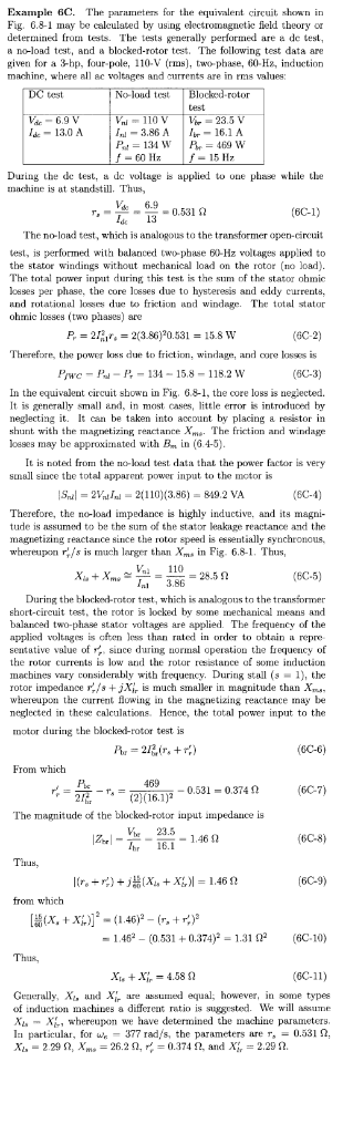
Example 6C. The parameters for the equivalent circuit shown in Fig. 6.8-1 may be calculated by using electromagnetie feld theory or deterined from tests. The tests generally performed are a de test, no-load test, and blocked-rotor test. The following test data are given for a 3-hp, four-pole, 110-V (rins), two phase, 60-H, induction machine, where all ac voltages and currents are in rms values: test No loud test 4-13.0 A |In-3.86 Allir-16.1 A 134 WP-469 W -60 Hz -15 H7 During the de test, a de voltage i applied to oue piase while the machine is at standstill. Thus, V6.9 13 The no-load test, which is analogous to the transformer open-circuit test, is performed with balanced two-phase 1Hz voltages applied to the stator windings without mechanical load on the rotor (no load). The total power input during this test is the sum of the stator obmic losses per phase, the core losses due to hysteresis and eddy currents, and rotation loes due to friction and windage. The total stator ohmic losses (two phases) are P2Ri 2(3.860.531 158 W (6C-2) Therefore, the powerloss due to friction, windage, and core losses is Piwc--P131-15.8- 118.2 W (6C-3) In the equivalent circuit sbown in Fig. 6.8-1, the ore loss is negiected. It is generally small and, in most cases, little erTOr is introduced by neglecting it. It can be taken into account by placing a resistor in shunt with the magnetizing reactanceXme- The friction and windage loeses may be approximated with B in (64-5) It is noted from the no-load test data that the small since the total apparent power input to the motor is power factor is very Sal-2Vn2110) (3.86) 849.2 VA (6C-4) Therefore, the noload impedance is highly inductive, and its magni- tude is assumed to be the sum of the stator leakage reactance and the magnetizing reactance since the rotor speed is essentially synchronous, whereupon rs is much larger than Xm in Fig. 6.8-1. Thus, Xu+x,no--=-=28.5 Ω (6C-5) 3.86 During the blocked-rotor test, which is analogous to the transformer ehort-circuit test, the rotor is locked by some mechanical means and balanced two-phase stator voltages are applied. The frequency of the applied voltnges is often less than ted in order to obtain a repre sentative value of since during normal operation the frequeucy of the rotor currents is low and the rotor resistance of some induction machines vary considerably with frequency. During stall s1), the rotor impedance rs is much smaller in magnitude than whereupon the current owing in the mnagnetizing reactance may be meglected in these calculations. Hence, the total power input to the motor during the blocked-rotor test is eC-6) From which 469 (6C-7) (2)(16.1)2-0.531-0.374 Ω The magnitude of the blocked-rotor input impedance is e 23.5 12,.--1.46 Ω Ihr 16.1 (6C-8) Thus, (6C-9) from which -1.46. (0.531 + 0.374)2 = 1.31 Ω2 (6C-10) Thus (6C-11) Geelly, X, and Xir are assumed equal; however, in some types of induction machines a diffcrent tioissuggrsted We will asume X whereupon we have determined the machine parameters. In particular, for w, 377 rad/s, the parameters are r, = 0.531 Ω. Xu-229 Ω, Xm»-26.2 Ω1 r. : 0.374 Ω, and X,-2.29 Ω.
Homework Answers
Add Answer to:
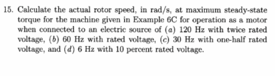
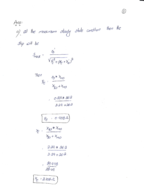
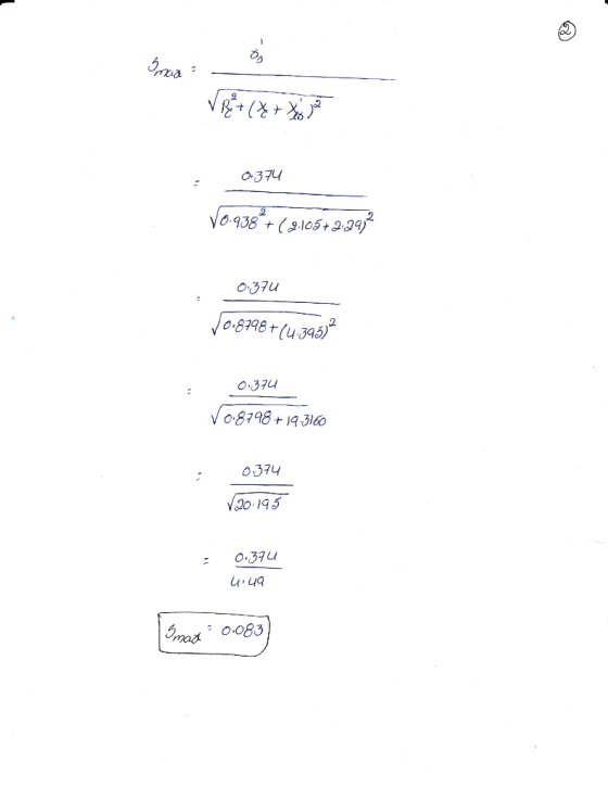
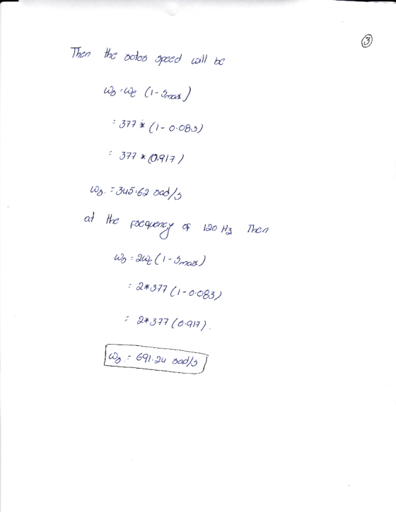
15. Calculate the actual rotor speed, in rad/s, at maximum steady-state torque for the machine gi...
5 Marks) A 4-pole, 3 phase, 50 Hz, 230 V induction motor. Each phase of rotor winding b) has one-fourth the number of t...
 5 Marks) A 4-pole, 3 phase, 50 Hz, 230 V induction motor. Each phase of rotor winding b) has one-fourth the number of turns of each stator. The full-load speed is 1,455 rpm. The rotor resistance is 0.3 Ω and rotor standstill reactance is 1.0 Ω per phase. The rotor and stator windings are similar. Stator losses are equal to 50 Watts. Friction and windage losses are equal to 30 W. Calculate ) Blocked rotor voltage per phase. 2 Marks)...
Name: 23. A 3-phase, 5000 hp, 6000 v,60 Hz, 12-pole wound-rotor induction motor has the 1, resistance between stator terminals-o12 Ω 2. resistance between rotor slip-rings-0.0073 Ω 3. windage and...
 Name: 23. A 3-phase, 5000 hp, 6000 v,60 Hz, 12-pole wound-rotor induction motor has the 1, resistance between stator terminals-o12 Ω 2. resistance between rotor slip-rings-0.0073 Ω 3. windage and friction losses-51 kW following characteristics 4. iron losses in the stator-39 kW 5. locked rotor current at 6000 V-1800 A 6. active power to the stator with rotor locked 2207 kw Calculate under full-load voltage locked-rotor conditions a. Reactive power absorbed by the motor b. FR losses in the stator...
5. (a) State the reason(s) for using a starter to start an induction motor. b) Describe,...
 5. (a) State the reason(s) for using a starter to start an induction motor. b) Describe, with the aid of diagram(s), two methods for starting of a squirrel cage induction (c) The results of no-load and blocked-rotor test on a 3-phase, star-connected induction motor are as follows No-load test: Line-to-Line voltage = 380V: Input power = 1500W: Block-rotor test: Line-to-Line voltage 38V; Input power - 2.4kW Input current-15A; Friction and windage losses is 500W Input current-65A. Stator resistance between terminal...
Problem Solving: 1. A 220V, 4-pole, 60Hz, 1-phase induction motor has an effective rotor resistance and...
 Problem Solving: 1. A 220V, 4-pole, 60Hz, 1-phase induction motor has an effective rotor resistance and leakage reactance of 0.5 Ohms and 5 ohms respectively. It is running at a speed of 1,800 rpm. Determine: a. Frequencies of forward and backward rotor current components b. Relative magnitudes of forward and backward fluxes. Neglect magnetizing current and stator impedance. A 220-W, 2-pole, 115-V, 60-Hz single-phase induction motor delivers rated output at a slip 10%. The total copper loss at full load...
A three-phase 4 pole wye connected 220 V, 15 Hp, 50 Hz induction machine (rated conditions) has t...
 A three-phase 4 pole wye connected 220 V, 15 Hp, 50 Hz induction machine (rated conditions) has the following parameters per phase refereed to the stator. RI : 0.29 Ω , R2 0. 14 Ω , Xi-0.50 Ω , X2-0.20 Ω , Xm-1 0.53 Ω The total windage and core losses can be assumed to be a constant 350 W. If the machine is operating at rated voltage and frequency with a 5.5% slip, find the steady-state: (a) 10pts. Mechanical...
5.7) An induction motor is installed in a factory. Under conditions in which the three-phase 415-volt...
 5.7) An induction motor is installed in a factory. Under conditions in which the three-phase 415-volt 50-Hz supply is perfectly balanced, the motor runs at 1492 rpm. A single-phase load is then energised elsewhere in the factory, which has the effect of reducing the supply voltage on phase "6" by 5% without changing its phase angle. It may be assumed that the motor's speed remains unchanged, and that the motor supply has no neutral conductor. The motor equivalent circuit parameters...
3ELEC 3600. Problem H8 3-phase Wound Rotor Induction Motor This sheet is page 1. Number all...
 3ELEC 3600. Problem H8 3-phase Wound Rotor Induction Motor This sheet is page 1. Number all pages. Consider the following induction machine THREE-PHASE INDUCTION MOTOR DATA* Ratings Line Voltage 2400 V; 72.17 A; Horsepower-300 hp stator frequency60 Hz Design W Poles -4; **Equivalent Circuit Values (in stator ohms Rated Freq)** R1 0.30000 R2'- 0.47159 X2'-1.73000; Jm2.5000 kg-m sq Thevenin Equivalent Circuit Values: RT-0.28524; slip, speed for max Torque0.1375; Rotational Loss Torque-TRL 0.18689 x (speed in rad/s) Nm X1 -1.73000 Xm67.740...
 5 Marks) A 4-pole, 3 phase, 50 Hz, 230 V induction motor. Each phase of rotor winding b) has one-fourth the number of turns of each stator. The full-load speed is 1,455 rpm. The rotor resistance is 0.3 Ω and rotor standstill reactance is 1.0 Ω per phase. The rotor and stator windings are similar. Stator losses are equal to 50 Watts. Friction and windage losses are equal to 30 W. Calculate ) Blocked rotor voltage per phase. 2 Marks)...
 Name: 23. A 3-phase, 5000 hp, 6000 v,60 Hz, 12-pole wound-rotor induction motor has the 1, resistance between stator terminals-o12 Ω 2. resistance between rotor slip-rings-0.0073 Ω 3. windage and friction losses-51 kW following characteristics 4. iron losses in the stator-39 kW 5. locked rotor current at 6000 V-1800 A 6. active power to the stator with rotor locked 2207 kw Calculate under full-load voltage locked-rotor conditions a. Reactive power absorbed by the motor b. FR losses in the stator...
 5. (a) State the reason(s) for using a starter to start an induction motor. b) Describe, with the aid of diagram(s), two methods for starting of a squirrel cage induction (c) The results of no-load and blocked-rotor test on a 3-phase, star-connected induction motor are as follows No-load test: Line-to-Line voltage = 380V: Input power = 1500W: Block-rotor test: Line-to-Line voltage 38V; Input power - 2.4kW Input current-15A; Friction and windage losses is 500W Input current-65A. Stator resistance between terminal...
 Problem Solving: 1. A 220V, 4-pole, 60Hz, 1-phase induction motor has an effective rotor resistance and leakage reactance of 0.5 Ohms and 5 ohms respectively. It is running at a speed of 1,800 rpm. Determine: a. Frequencies of forward and backward rotor current components b. Relative magnitudes of forward and backward fluxes. Neglect magnetizing current and stator impedance. A 220-W, 2-pole, 115-V, 60-Hz single-phase induction motor delivers rated output at a slip 10%. The total copper loss at full load...
 A three-phase 4 pole wye connected 220 V, 15 Hp, 50 Hz induction machine (rated conditions) has the following parameters per phase refereed to the stator. RI : 0.29 Ω , R2 0. 14 Ω , Xi-0.50 Ω , X2-0.20 Ω , Xm-1 0.53 Ω The total windage and core losses can be assumed to be a constant 350 W. If the machine is operating at rated voltage and frequency with a 5.5% slip, find the steady-state: (a) 10pts. Mechanical...
 5.7) An induction motor is installed in a factory. Under conditions in which the three-phase 415-volt 50-Hz supply is perfectly balanced, the motor runs at 1492 rpm. A single-phase load is then energised elsewhere in the factory, which has the effect of reducing the supply voltage on phase "6" by 5% without changing its phase angle. It may be assumed that the motor's speed remains unchanged, and that the motor supply has no neutral conductor. The motor equivalent circuit parameters...
 3ELEC 3600. Problem H8 3-phase Wound Rotor Induction Motor This sheet is page 1. Number all pages. Consider the following induction machine THREE-PHASE INDUCTION MOTOR DATA* Ratings Line Voltage 2400 V; 72.17 A; Horsepower-300 hp stator frequency60 Hz Design W Poles -4; **Equivalent Circuit Values (in stator ohms Rated Freq)** R1 0.30000 R2'- 0.47159 X2'-1.73000; Jm2.5000 kg-m sq Thevenin Equivalent Circuit Values: RT-0.28524; slip, speed for max Torque0.1375; Rotational Loss Torque-TRL 0.18689 x (speed in rad/s) Nm X1 -1.73000 Xm67.740...
Most questions answered within 3 hours.
-
Please answer true or false. Words
cannot be changed or added in to make it true...
asked 49 minutes ago -
An empty test tube weighs 15.923 grams. Then,
MgCl2•6H2O is added into the test tube. After...
asked 50 minutes ago -
(a) A piston at 6.1 atm contains a gas that occupies a volume of
3.5 L....
asked 50 minutes ago -
Assume memory access is 10 units of time and disk access is
10000 units of time....
asked 1 hour ago -
1. Are all good samples random?
2. Magazines often report surveys giving statistics such as “63%...
asked 1 hour ago -
Under all the various types of market structures, firms
must eventually earn some economic profits for...
asked 1 hour ago -
Consider the following fitness regime for a single locus trait
with two co-dominant alleles: w11 =...
asked 1 hour ago -
A large cable company reports the following.
80% of its customers subscribe to its cable TV...
asked 1 hour ago -
Please answer the question in brief.
Discuss the role of ERP in organizations. Are ERP tools...
asked 1 hour ago -
Discuss the pros and cons of collaborative software such
as SameTime. Does it increase productivity? What...
asked 1 hour ago -
Buying your in-laws a gift because it’s expected is
due to the ____________ motive of gift-giving....
asked 1 hour ago -
Calculate the expected value, the variance, and the standard
deviation of the given random variable X....
asked 2 hours ago