

please help ASAP
The properties of a aterial in shear can be determined direct-shear tests or from torsison cests แคฮ through th8 Hookes ow in sherceest s it s in enslion. This Inearly elaste region obeys Gy E 1-21 in which G is the shear modulus of elosticity (a The moduli callted the modulus of rigidity of elasticity in tension and shear are related by the zaE 1-22 1.7-10 A flexible connection consisting of rubber pads (thickness t9 mm) bonded to steel plates is shown in the figure. The pads are 160 mm long and 80 imin wide. (a) Find the average shear strain %-in the rubber if the force P = 16 kN and the shear modulus for the rubber is G 1250 kPa. (b) Find the relative horizontal displacement 5 between the interior plate and the outer plates 60 mm Rubber pod Rubber pad 80 mm : 9 mm Section X-x
1.3-S A long retaining wall is braced by wood shores set at an angle of 30P and supported by concrete thrust blocks, as shown in the first part of the figure The shotes are evenly spaced, 3 m apart For analysis purposes, the wall and shores are ideal- zed as shown in the secoed part of the figure. Note that the base of the wall and both ends of the shores are assumed to be pinned. The pressare of the soil against the wall is assumed to be tria force acting on a 3-meter length of the wall is F190 kN distributed, and the resultant If each shore has a 150 mo X150 mn square crOSS section, what is the compressive stress a, in the shores? Soil Retaining wall Shore thrust block SC 4.0m PROB. 1.3-s
Homework Answers


Add Answer to:
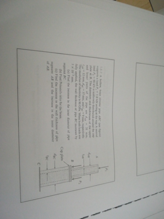
1.5-7 A hollow, brass circular pipe ABC (oce figure supports a load P, 118 kN acting at the top A...
1. [30 pt.] A hollow circular post ABC (see figure) supports a load P 1700 lb acting at the top. ...
 1. [30 pt.] A hollow circular post ABC (see figure) supports a load P 1700 lb acting at the top. A second load P2 is uniformly distributed around the cap plate at B. The diameters and thicknesses of the upper and lower parts of the post are das 1.25 in., tAB 0.5 in., dec 2.25 in., andc 0.375 in., respectively (a) Calculate the normal stress ơAB in the upper part of the post. (b) If it is desired that the...
A 3 m rigid bar AB is supported with a vertical translational spring at A and a pin at B The bar is subjected to a linearly varying distributed load with maximum intensity g Calculate the ver...
 A 3 m rigid bar AB is supported with a vertical translational spring at A and a pin at B The bar is subjected to a linearly varying distributed load with maximum intensity g Calculate the vertical deformation of the spring if the spring constant is 700 kN/m. (ans: 21.43 mm) 2. A steel cable with a nominal diameter of 25 mm is used in a construction yard to lift a bridge section weighing 38 kN. The cable has an...
 1. [30 pt.] A hollow circular post ABC (see figure) supports a load P 1700 lb acting at the top. A second load P2 is uniformly distributed around the cap plate at B. The diameters and thicknesses of the upper and lower parts of the post are das 1.25 in., tAB 0.5 in., dec 2.25 in., andc 0.375 in., respectively (a) Calculate the normal stress ơAB in the upper part of the post. (b) If it is desired that the...
 A 3 m rigid bar AB is supported with a vertical translational spring at A and a pin at B The bar is subjected to a linearly varying distributed load with maximum intensity g Calculate the vertical deformation of the spring if the spring constant is 700 kN/m. (ans: 21.43 mm) 2. A steel cable with a nominal diameter of 25 mm is used in a construction yard to lift a bridge section weighing 38 kN. The cable has an...
Most questions answered within 3 hours.
-
The average length of time between arrivals at a turnpike
toll-booth is 26 seconds. What is...
asked 50 minutes ago -
(a) A piston at 6.1 atm contains a gas that occupies a volume of
3.5 L....
asked 2 hours ago -
Please answer true or false. Words
cannot be changed or added in to make it true...
asked 2 hours ago -
An empty test tube weighs 15.923 grams. Then,
MgCl2•6H2O is added into the test tube. After...
asked 2 hours ago -
Assume memory access is 10 units of time and disk access is
10000 units of time....
asked 2 hours ago -
1. Are all good samples random?
2. Magazines often report surveys giving statistics such as “63%...
asked 2 hours ago -
Under all the various types of market structures, firms
must eventually earn some economic profits for...
asked 2 hours ago -
Consider the following fitness regime for a single locus trait
with two co-dominant alleles: w11 =...
asked 2 hours ago -
A large cable company reports the following.
80% of its customers subscribe to its cable TV...
asked 2 hours ago -
Please answer the question in brief.
Discuss the role of ERP in organizations. Are ERP tools...
asked 2 hours ago -
Discuss the pros and cons of collaborative software such
as SameTime. Does it increase productivity? What...
asked 2 hours ago -
Buying your in-laws a gift because it’s expected is
due to the ____________ motive of gift-giving....
asked 2 hours ago