
Homework Answers

Add Answer to:
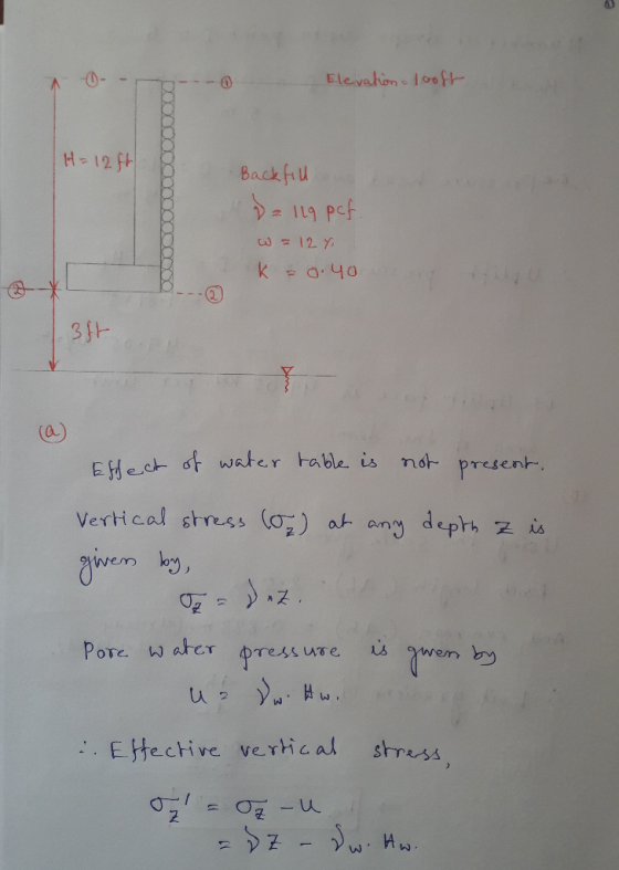
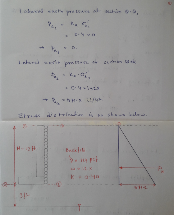
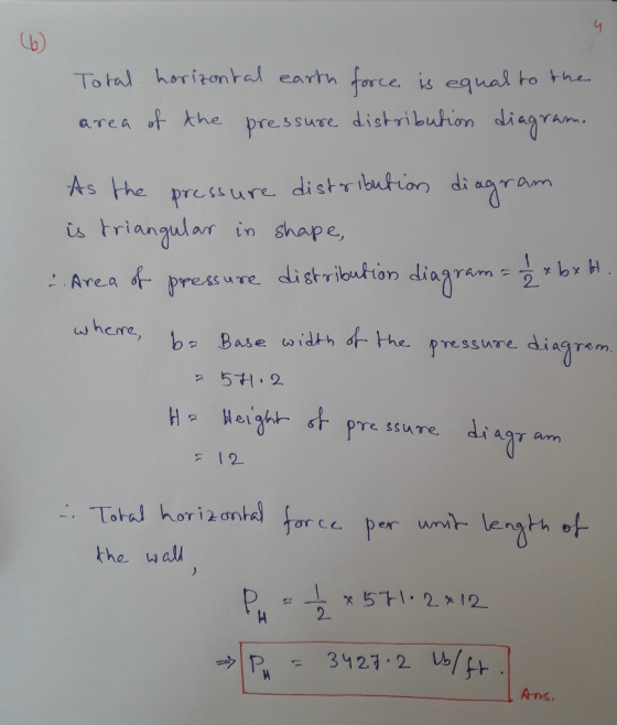
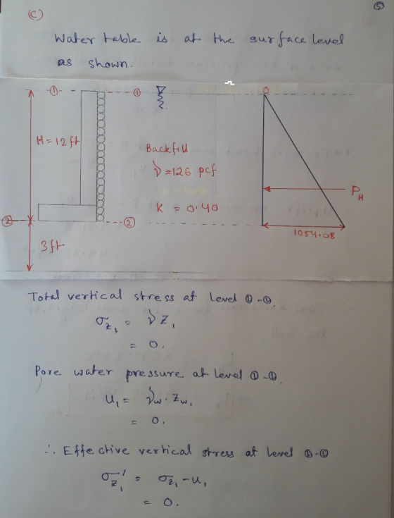
Problem 5 You are to examine the retaining wall shown on Figure 2. Assume that the wall height (H...
You have to review the design of a cantilevered concrete retaining wall designed for the height a...
 You have to review the design of a cantilevered concrete retaining wall designed for the height and soil as shown in the figure. Please check the design and provide your recommendation for the following situation: - 200 psf Surcharge load on top of the backfill material Lean clay at foundation same soil for backfill Dry unit weight of soil Cohesion/adhesion of the clay/concrete Bearing capacity of the soil Active earth pressure coefficient Ignore the effect of ground water table Unit...
(2) A retaining wall is designed for free-draining granular backfill, as shown below. The coefficient of...
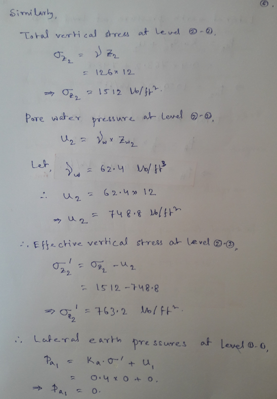
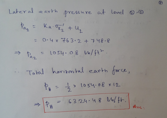
 (2) A retaining wall is designed for free-draining granular backfill, as shown below. The coefficient of at-rest earth pressure, Ko0.307. After several years operation, the weepholes becomes plugged and the water table rises to within 10 ft of the top of the wall. Determine (a) The resultant force for the drained case and the location of the resultant force? (b) The resultant force for the plugged case and the location of the resultant force? 10 ft dry -102 lbf/ft3 Ydry...
( You do not have to solve number 2. I need number 3.) Problem 2(15 points). Refer...
 ( You do not have to solve number 2. I need
number 3.)
Problem 2(15 points). Refer to Figure 2 below. Given the height of the retaining wall, H is 18ft, the backfill is a saturated clay with, ф, 0°, c-500 lb/ft, Y-120 lb/ft. sat (a) Determine the Rankine active pressure distribution diagram behind the wall. Determine the depth of the tensile crack, zc (c) Estimate the Rankine active force per foot length of the wall before and after the occurrence...
( You do not have to solve number 2. I need
number 3.)
Problem 2(15 points). Refer to Figure 2 below. Given the height of the retaining wall, H is 18ft, the backfill is a saturated clay with, ф, 0°, c-500 lb/ft, Y-120 lb/ft. sat (a) Determine the Rankine active pressure distribution diagram behind the wall. Determine the depth of the tensile crack, zc (c) Estimate the Rankine active force per foot length of the wall before and after the occurrence...
A gravity retaining wall is shown in figure. Use Rankine active earth pressure theory. Determine: a. The factor of safety against overturning b. The factor of safety against sliding c. The factor of safety for bearing capacity d. The pressure on the soil
 A gravity retaining wall is shown in figure. Use Rankine active earth pressure theory. Determine:a. The factor of safety against overturningb. The factor of safety against slidingc. The factor of safety for bearing capacityd. The pressure on the soil at the toe and heelAssume, γconcrete = 24 kN/m3. Also, consider the weight of the soil behind the wall and consider the passive earth pressure.
Problem 2 130 points) A gravity cantilever wall is being designed to contain water in a canal, as shown in Figure 3.3 (Note: There is water only on the left side of the wall, there is no water un...
 Problem 2 130 points) A gravity cantilever wall is being designed to contain water in a canal, as shown in Figure 3.3 (Note: There is water only on the left side of the wall, there is no water underneath the base of the wall and on the right side of the wall. 0.8 m Water -10kN/m 4.0m Clay 1.0m (No water) 2.0m 4-39 Concrete -16kN/m Dense gravelly sand (No water) e-仰 5.0m Figure 3-Gravity cantilever wall and material properties Regarding...
A 17.0-m-high wall is under construction and its bracing is shown in the figure. This is...
 A 17.0-m-high wall is under construction and its bracing is shown in the figure. This is the bracing per foot along the length of the wall. The wall is in static equilibrium but needs the bracing to withstand wind pressure. It can pivot at its base. Fwind 17.0m 8.5 m 359 Calculate the force exerted by the brace if a strong wind exerts a horizontal force of 650 N on the wall. Assume that the net force from the wind...
Sove for part 1 CV 5263 HW 1 (2018-19) Name: Problem 2: Lateral Earth Pressure Theories...
 Sove for part 1
CV 5263 HW 1 (2018-19) Name: Problem 2: Lateral Earth Pressure Theories For both part 1 and part 2 determine: Magnitude of active resultant force per length of wall Location (height) of the active resultant force from the base of wall Direction (angle above horizontal) of the active resultant force Horizontal component of the active resultant force per length of wall Vertical component of the active resultant force per length of wall . Part 1: Coulomb...
Sove for part 1
CV 5263 HW 1 (2018-19) Name: Problem 2: Lateral Earth Pressure Theories For both part 1 and part 2 determine: Magnitude of active resultant force per length of wall Location (height) of the active resultant force from the base of wall Direction (angle above horizontal) of the active resultant force Horizontal component of the active resultant force per length of wall Vertical component of the active resultant force per length of wall . Part 1: Coulomb...
Solve part 2, CV 5263 HW 1 (2018-19) Name: Problem 2: Lateral Earth Pressure Theories For...
 Solve part 2,
CV 5263 HW 1 (2018-19) Name: Problem 2: Lateral Earth Pressure Theories For both part 1 and part 2 determine: e Magnitude of active resultant force per length of wall e Location (height) of the active resultant force from the base of wall Direction (angle above horizontal) of the active resultant force Horizontal component of the active resultant force per length of wall Vertical component of the active resultant force per length of wall . Part 1:...
Solve part 2,
CV 5263 HW 1 (2018-19) Name: Problem 2: Lateral Earth Pressure Theories For both part 1 and part 2 determine: e Magnitude of active resultant force per length of wall e Location (height) of the active resultant force from the base of wall Direction (angle above horizontal) of the active resultant force Horizontal component of the active resultant force per length of wall Vertical component of the active resultant force per length of wall . Part 1:...
 You have to review the design of a cantilevered concrete retaining wall designed for the height and soil as shown in the figure. Please check the design and provide your recommendation for the following situation: - 200 psf Surcharge load on top of the backfill material Lean clay at foundation same soil for backfill Dry unit weight of soil Cohesion/adhesion of the clay/concrete Bearing capacity of the soil Active earth pressure coefficient Ignore the effect of ground water table Unit...
 (2) A retaining wall is designed for free-draining granular backfill, as shown below. The coefficient of at-rest earth pressure, Ko0.307. After several years operation, the weepholes becomes plugged and the water table rises to within 10 ft of the top of the wall. Determine (a) The resultant force for the drained case and the location of the resultant force? (b) The resultant force for the plugged case and the location of the resultant force? 10 ft dry -102 lbf/ft3 Ydry...
 ( You do not have to solve number 2. I need
number 3.)
Problem 2(15 points). Refer to Figure 2 below. Given the height of the retaining wall, H is 18ft, the backfill is a saturated clay with, ф, 0°, c-500 lb/ft, Y-120 lb/ft. sat (a) Determine the Rankine active pressure distribution diagram behind the wall. Determine the depth of the tensile crack, zc (c) Estimate the Rankine active force per foot length of the wall before and after the occurrence...
( You do not have to solve number 2. I need
number 3.)
Problem 2(15 points). Refer to Figure 2 below. Given the height of the retaining wall, H is 18ft, the backfill is a saturated clay with, ф, 0°, c-500 lb/ft, Y-120 lb/ft. sat (a) Determine the Rankine active pressure distribution diagram behind the wall. Determine the depth of the tensile crack, zc (c) Estimate the Rankine active force per foot length of the wall before and after the occurrence...
 Problem 2 130 points) A gravity cantilever wall is being designed to contain water in a canal, as shown in Figure 3.3 (Note: There is water only on the left side of the wall, there is no water underneath the base of the wall and on the right side of the wall. 0.8 m Water -10kN/m 4.0m Clay 1.0m (No water) 2.0m 4-39 Concrete -16kN/m Dense gravelly sand (No water) e-仰 5.0m Figure 3-Gravity cantilever wall and material properties Regarding...
 A 17.0-m-high wall is under construction and its bracing is shown in the figure. This is the bracing per foot along the length of the wall. The wall is in static equilibrium but needs the bracing to withstand wind pressure. It can pivot at its base. Fwind 17.0m 8.5 m 359 Calculate the force exerted by the brace if a strong wind exerts a horizontal force of 650 N on the wall. Assume that the net force from the wind...
 Sove for part 1
CV 5263 HW 1 (2018-19) Name: Problem 2: Lateral Earth Pressure Theories For both part 1 and part 2 determine: Magnitude of active resultant force per length of wall Location (height) of the active resultant force from the base of wall Direction (angle above horizontal) of the active resultant force Horizontal component of the active resultant force per length of wall Vertical component of the active resultant force per length of wall . Part 1: Coulomb...
Sove for part 1
CV 5263 HW 1 (2018-19) Name: Problem 2: Lateral Earth Pressure Theories For both part 1 and part 2 determine: Magnitude of active resultant force per length of wall Location (height) of the active resultant force from the base of wall Direction (angle above horizontal) of the active resultant force Horizontal component of the active resultant force per length of wall Vertical component of the active resultant force per length of wall . Part 1: Coulomb...
 Solve part 2,
CV 5263 HW 1 (2018-19) Name: Problem 2: Lateral Earth Pressure Theories For both part 1 and part 2 determine: e Magnitude of active resultant force per length of wall e Location (height) of the active resultant force from the base of wall Direction (angle above horizontal) of the active resultant force Horizontal component of the active resultant force per length of wall Vertical component of the active resultant force per length of wall . Part 1:...
Solve part 2,
CV 5263 HW 1 (2018-19) Name: Problem 2: Lateral Earth Pressure Theories For both part 1 and part 2 determine: e Magnitude of active resultant force per length of wall e Location (height) of the active resultant force from the base of wall Direction (angle above horizontal) of the active resultant force Horizontal component of the active resultant force per length of wall Vertical component of the active resultant force per length of wall . Part 1:...
Most questions answered within 3 hours.
-
An FM modulator is tested using
single-tone baseband signal with frequency of 50kHz and a sprectrum...
asked 13 minutes ago -
Write the ionic equations for the first stage of salts
hydrolysis.
Anion, Cation?
Na2S
NiSO4
K2SO4...
asked 1 hour ago -
suppose there is a normally distributed population with a mean of
250 and a standard deviation...
asked 2 hours ago -
Question Three
Suppose you as project manager are using the Waterfall
development methodology on a large...
asked 3 hours ago -
Which statement is not true about welfare in Canada?
A.Benefits typically vary based on one's ability...
asked 4 hours ago -
Please help me with FLOWCHART and UML diagram for class,
thank you!
#include <iostream>
#include <fstream>...
asked 4 hours ago -
3. Describe the “logic circuit” of the Lac operon. Which
proteins are bound or not to...
asked 4 hours ago -
Ayesha’s adjusted gross income is $60,000 in 2019. She donated a
piece of artwork with a...
asked 4 hours ago -
For Dijkstra’s shortest path algorithm:
a. Give the Big-O time for Dijkstra’s shortest path algorithm
and...
asked 5 hours ago -
Phosphorus violates the 'octet rule' in biological molecules,
forming more covalent bonds than expected based on...
asked 5 hours ago -
A 1.3 eV electron has a 10-4 probability of tunneling
through a 2.4 eV potential barrier....
asked 5 hours ago -
What is the one ingredient that is common to being successful
with all stakeholders?
profit
trust...
asked 5 hours ago