
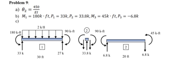
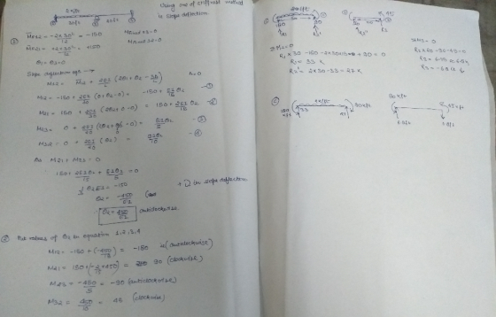
Problem 9: 450 a) θ2_El b) M1 180k ft,P133k, P2 33.8k, M3 45k ft, P3 -6.8k c) 2 90 k-ft 45 k-ft 180 k-ft 33.8 k6.8 k 6.8 k 27 k 33 k 20 ft 30 ft
Homework Answers
Add Answer to:
Problem 9: Consider the statically indeterminate beam shown below with the given loading. E and I...
Please show work Answer shown below Problem 8: Consider the statically indeterminate beam shown below with...
 Please show work
Answer shown below
Problem 8: Consider the statically indeterminate beam shown below with the given loading. E and I are constant. a) Find the rotation at node 2 using the stiffness method. b) Find the unknown reactions using equilibrium and the force-displacement relationships. Draw final free body diagrams of the two beam elements and node 2, showing all forces with the correct values and directions. c) 2.5 k/ft 30 ft 20 ft Problem : θ2=562.5k-ft2 rad a)...
Please show work
Answer shown below
Problem 8: Consider the statically indeterminate beam shown below with the given loading. E and I are constant. a) Find the rotation at node 2 using the stiffness method. b) Find the unknown reactions using equilibrium and the force-displacement relationships. Draw final free body diagrams of the two beam elements and node 2, showing all forces with the correct values and directions. c) 2.5 k/ft 30 ft 20 ft Problem : θ2=562.5k-ft2 rad a)...
Problem 7: Consider the statically indeterminate beam shown below with the given loading. E- 29,000 ksi...
 Problem 7: Consider the statically indeterminate beam shown below with the given loading. E- 29,000 ksi and I- 600 in a) Use the stiffness method to find the rotation at node 1. b) Determine the unknown reactions using the force-displacement relationships. c) Draw the shear and moment diagrams for the beam. 12 k 2
Please show work Answer shown below Problem 7: Consider the statically indeterminate beam shown below with...
 Please show work
Answer shown below
Problem 7: Consider the statically indeterminate beam shown below with the given loading. E-29,000 ksi and I-600 in. Use the stiffness method to find the rotation at node1 Draw the shear and moment diagrams for the beam. 12 k a) c) 18 ft Problem 7: a) 82.01 x 10⁻³rad b) P7.6k, M2-33.7k ft, P2 4.4k c) 7.0 4.4 45.6 33.7
Please show work
Answer shown below
Problem 7: Consider the statically indeterminate beam shown below with the given loading. E-29,000 ksi and I-600 in. Use the stiffness method to find the rotation at node1 Draw the shear and moment diagrams for the beam. 12 k a) c) 18 ft Problem 7: a) 82.01 x 10⁻³rad b) P7.6k, M2-33.7k ft, P2 4.4k c) 7.0 4.4 45.6 33.7
Problem 3: The statically indeterminate propped cantilever beam is supported by a roller at A and...
 Problem 3: The statically indeterminate propped cantilever beam is supported by a roller at A and is fixed at B. The beam is subject a uniformly distributed load and concentrated moment as shown. E is 29000 ksi and 1 is 400 in Determine the equation of the moment as a function of x. b) a) Determine the equations of the beam slope and deflection as a functions ofx (do not substitute the values of E and I c) Find slope...
Please show work Answer shown below Problem 5: Consider the continuous beam structure shown below. For...
 Please show work
Answer shown below
Problem 5: Consider the continuous beam structure shown below. For each node, state the force/moment and displacement/rotation boundary conditions required to properly set-up a solution by the stiffness method. Indicate unknown values with a "u 24 k 125 k-ft 200 k-ft Problem 5: M1 200k ft P1 24 k M2 0 k ft 1-u 0,- u Ma = 125k . ft 3-u
Please show work
Answer shown below
Problem 5: Consider the continuous beam structure shown below. For each node, state the force/moment and displacement/rotation boundary conditions required to properly set-up a solution by the stiffness method. Indicate unknown values with a "u 24 k 125 k-ft 200 k-ft Problem 5: M1 200k ft P1 24 k M2 0 k ft 1-u 0,- u Ma = 125k . ft 3-u
2) Consider a statically indeterminate beam in (I) = (i) + (ii) + (iii) as shown. a) Using your cheat sheet, compute the solutions of (i), (ii) and (iii) (A to B) respectively in terms of w0, P...
 2) Consider a statically indeterminate beam in
(I) = (i) + (ii) + (iii) as shown.
a) Using your cheat
sheet, compute the solutions of (i), (ii)
and (iii) (A to B) respectively
in terms of w0, P and
Q.
b) Compute for (i), (ii) and (iii) at the free end B.
b) Impose the constraint at B to solve
for the reaction
Q=RB
(<0) at B.
c) Find the elastic curve of
(I), the (+2)force & moment
reactions at...
2) Consider a statically indeterminate beam in
(I) = (i) + (ii) + (iii) as shown.
a) Using your cheat
sheet, compute the solutions of (i), (ii)
and (iii) (A to B) respectively
in terms of w0, P and
Q.
b) Compute for (i), (ii) and (iii) at the free end B.
b) Impose the constraint at B to solve
for the reaction
Q=RB
(<0) at B.
c) Find the elastic curve of
(I), the (+2)force & moment
reactions at...
Please find all reactions with Moment Distribution Method & draw shear/moment diagrams. Please show all work. Thank you in advance! Problem #2: For the indeterminate beam shown below: a) Determin...
 Please find all reactions with Moment Distribution Method &
draw shear/moment diagrams. Please show all work. Thank you in
advance!
Problem #2: For the indeterminate beam shown below: a) Determine all reactions using the Moment Distribution Method. b) Draw shear and moment diagrams. El is constant. Show your work. 18 kips 24 kips 6 k/ft 16 k/ft 10ft 12 ft 12ft
Problem #2: For the indeterminate beam shown below: a) Determine all reactions using the Moment Distribution Method. b) Draw...
Please find all reactions with Moment Distribution Method &
draw shear/moment diagrams. Please show all work. Thank you in
advance!
Problem #2: For the indeterminate beam shown below: a) Determine all reactions using the Moment Distribution Method. b) Draw shear and moment diagrams. El is constant. Show your work. 18 kips 24 kips 6 k/ft 16 k/ft 10ft 12 ft 12ft
Problem #2: For the indeterminate beam shown below: a) Determine all reactions using the Moment Distribution Method. b) Draw...
Problem 1: Given: The beam with a concentrated load shown below. a 10 ft, b 15 ft. Find: Draw the internal shear fo...
 Problem 1: Given: The beam with a concentrated load shown below. a 10 ft, b 15 ft. Find: Draw the internal shear force and bending moment diagrams. Use the standard sign convention. Draw clear, complete and accurate Free Body Diagrams! 5 k
Problem 1: Given: The beam with a concentrated load shown below. a 10 ft, b 15 ft. Find: Draw the internal shear force and bending moment diagrams. Use the standard sign convention. Draw clear, complete and accurate Free...
Problem 1: Given: The beam with a concentrated load shown below. a 10 ft, b 15 ft. Find: Draw the internal shear force and bending moment diagrams. Use the standard sign convention. Draw clear, complete and accurate Free Body Diagrams! 5 k
Problem 1: Given: The beam with a concentrated load shown below. a 10 ft, b 15 ft. Find: Draw the internal shear force and bending moment diagrams. Use the standard sign convention. Draw clear, complete and accurate Free...
Please show work Answer shown below Problem 2: Consider the three-spring structure given below. It is...
 Please show work
Answer shown below
Problem 2: Consider the three-spring structure given below. It is fixed at the far right end (node 4) and is subject to nodal forces as given below. из 144 lu 142 Pi Kj Ki P2 The element (spring) stiffnesses are: Ki- K2- 200 k/in and Ks-250 k/in The forces applied at the nodes are: P 150 k, P--50 k, Ps 150 k E.g. the stiffness a) Write the stiffness equilibrium equations for nodes 1,...
Please show work
Answer shown below
Problem 2: Consider the three-spring structure given below. It is fixed at the far right end (node 4) and is subject to nodal forces as given below. из 144 lu 142 Pi Kj Ki P2 The element (spring) stiffnesses are: Ki- K2- 200 k/in and Ks-250 k/in The forces applied at the nodes are: P 150 k, P--50 k, Ps 150 k E.g. the stiffness a) Write the stiffness equilibrium equations for nodes 1,...
Homework Problem H 7.E Consider the truss shown below with the loading on joints D, K, S and U. Given: Find: For this p...
 Homework Problem H 7.E Consider the truss shown below with the loading on joints D, K, S and U. Given: Find: For this problem: a) Determine the external reactions acting on the truss at supports A and H b) Identify all zero-force members in the truss. c) Determine the load carried by members BC, CJ and MN. Identify each member as either being in tension, in compression or carrying zero load. For this problem, use the following parameters: h 30...
 Please show work
Answer shown below
Problem 8: Consider the statically indeterminate beam shown below with the given loading. E and I are constant. a) Find the rotation at node 2 using the stiffness method. b) Find the unknown reactions using equilibrium and the force-displacement relationships. Draw final free body diagrams of the two beam elements and node 2, showing all forces with the correct values and directions. c) 2.5 k/ft 30 ft 20 ft Problem : θ2=562.5k-ft2 rad a)...
Please show work
Answer shown below
Problem 8: Consider the statically indeterminate beam shown below with the given loading. E and I are constant. a) Find the rotation at node 2 using the stiffness method. b) Find the unknown reactions using equilibrium and the force-displacement relationships. Draw final free body diagrams of the two beam elements and node 2, showing all forces with the correct values and directions. c) 2.5 k/ft 30 ft 20 ft Problem : θ2=562.5k-ft2 rad a)...
 Problem 7: Consider the statically indeterminate beam shown below with the given loading. E- 29,000 ksi and I- 600 in a) Use the stiffness method to find the rotation at node 1. b) Determine the unknown reactions using the force-displacement relationships. c) Draw the shear and moment diagrams for the beam. 12 k 2
 Please show work
Answer shown below
Problem 7: Consider the statically indeterminate beam shown below with the given loading. E-29,000 ksi and I-600 in. Use the stiffness method to find the rotation at node1 Draw the shear and moment diagrams for the beam. 12 k a) c) 18 ft Problem 7: a) 82.01 x 10⁻³rad b) P7.6k, M2-33.7k ft, P2 4.4k c) 7.0 4.4 45.6 33.7
Please show work
Answer shown below
Problem 7: Consider the statically indeterminate beam shown below with the given loading. E-29,000 ksi and I-600 in. Use the stiffness method to find the rotation at node1 Draw the shear and moment diagrams for the beam. 12 k a) c) 18 ft Problem 7: a) 82.01 x 10⁻³rad b) P7.6k, M2-33.7k ft, P2 4.4k c) 7.0 4.4 45.6 33.7
 Problem 3: The statically indeterminate propped cantilever beam is supported by a roller at A and is fixed at B. The beam is subject a uniformly distributed load and concentrated moment as shown. E is 29000 ksi and 1 is 400 in Determine the equation of the moment as a function of x. b) a) Determine the equations of the beam slope and deflection as a functions ofx (do not substitute the values of E and I c) Find slope...
 Please show work
Answer shown below
Problem 5: Consider the continuous beam structure shown below. For each node, state the force/moment and displacement/rotation boundary conditions required to properly set-up a solution by the stiffness method. Indicate unknown values with a "u 24 k 125 k-ft 200 k-ft Problem 5: M1 200k ft P1 24 k M2 0 k ft 1-u 0,- u Ma = 125k . ft 3-u
Please show work
Answer shown below
Problem 5: Consider the continuous beam structure shown below. For each node, state the force/moment and displacement/rotation boundary conditions required to properly set-up a solution by the stiffness method. Indicate unknown values with a "u 24 k 125 k-ft 200 k-ft Problem 5: M1 200k ft P1 24 k M2 0 k ft 1-u 0,- u Ma = 125k . ft 3-u
 2) Consider a statically indeterminate beam in
(I) = (i) + (ii) + (iii) as shown.
a) Using your cheat
sheet, compute the solutions of (i), (ii)
and (iii) (A to B) respectively
in terms of w0, P and
Q.
b) Compute for (i), (ii) and (iii) at the free end B.
b) Impose the constraint at B to solve
for the reaction
Q=RB
(<0) at B.
c) Find the elastic curve of
(I), the (+2)force & moment
reactions at...
2) Consider a statically indeterminate beam in
(I) = (i) + (ii) + (iii) as shown.
a) Using your cheat
sheet, compute the solutions of (i), (ii)
and (iii) (A to B) respectively
in terms of w0, P and
Q.
b) Compute for (i), (ii) and (iii) at the free end B.
b) Impose the constraint at B to solve
for the reaction
Q=RB
(<0) at B.
c) Find the elastic curve of
(I), the (+2)force & moment
reactions at...
 Please find all reactions with Moment Distribution Method &
draw shear/moment diagrams. Please show all work. Thank you in
advance!
Problem #2: For the indeterminate beam shown below: a) Determine all reactions using the Moment Distribution Method. b) Draw shear and moment diagrams. El is constant. Show your work. 18 kips 24 kips 6 k/ft 16 k/ft 10ft 12 ft 12ft
Problem #2: For the indeterminate beam shown below: a) Determine all reactions using the Moment Distribution Method. b) Draw...
Please find all reactions with Moment Distribution Method &
draw shear/moment diagrams. Please show all work. Thank you in
advance!
Problem #2: For the indeterminate beam shown below: a) Determine all reactions using the Moment Distribution Method. b) Draw shear and moment diagrams. El is constant. Show your work. 18 kips 24 kips 6 k/ft 16 k/ft 10ft 12 ft 12ft
Problem #2: For the indeterminate beam shown below: a) Determine all reactions using the Moment Distribution Method. b) Draw...
 Problem 1: Given: The beam with a concentrated load shown below. a 10 ft, b 15 ft. Find: Draw the internal shear force and bending moment diagrams. Use the standard sign convention. Draw clear, complete and accurate Free Body Diagrams! 5 k
Problem 1: Given: The beam with a concentrated load shown below. a 10 ft, b 15 ft. Find: Draw the internal shear force and bending moment diagrams. Use the standard sign convention. Draw clear, complete and accurate Free...
Problem 1: Given: The beam with a concentrated load shown below. a 10 ft, b 15 ft. Find: Draw the internal shear force and bending moment diagrams. Use the standard sign convention. Draw clear, complete and accurate Free Body Diagrams! 5 k
Problem 1: Given: The beam with a concentrated load shown below. a 10 ft, b 15 ft. Find: Draw the internal shear force and bending moment diagrams. Use the standard sign convention. Draw clear, complete and accurate Free...
 Please show work
Answer shown below
Problem 2: Consider the three-spring structure given below. It is fixed at the far right end (node 4) and is subject to nodal forces as given below. из 144 lu 142 Pi Kj Ki P2 The element (spring) stiffnesses are: Ki- K2- 200 k/in and Ks-250 k/in The forces applied at the nodes are: P 150 k, P--50 k, Ps 150 k E.g. the stiffness a) Write the stiffness equilibrium equations for nodes 1,...
Please show work
Answer shown below
Problem 2: Consider the three-spring structure given below. It is fixed at the far right end (node 4) and is subject to nodal forces as given below. из 144 lu 142 Pi Kj Ki P2 The element (spring) stiffnesses are: Ki- K2- 200 k/in and Ks-250 k/in The forces applied at the nodes are: P 150 k, P--50 k, Ps 150 k E.g. the stiffness a) Write the stiffness equilibrium equations for nodes 1,...
 Homework Problem H 7.E Consider the truss shown below with the loading on joints D, K, S and U. Given: Find: For this problem: a) Determine the external reactions acting on the truss at supports A and H b) Identify all zero-force members in the truss. c) Determine the load carried by members BC, CJ and MN. Identify each member as either being in tension, in compression or carrying zero load. For this problem, use the following parameters: h 30...
Most questions answered within 3 hours.
-
Using C++ :
A Pascals triangle row is constructed by looking at the previous
row and...
asked 4 minutes ago -
With what speed will the fastest photoelectrons be emitted from
a surface whose threshold wavelength is...
asked 4 minutes ago -
The following slope distances and differences in elevations
between the tape ends were recorded for a...
asked 6 minutes ago -
1. Assuming random walk markets and normally distributed
returns, if a one day VaR on an...
asked 15 minutes ago -
(a) With a variable life insurance policy, the rate of return on
the investment (the death...
asked 25 minutes ago -
By applying what you know about Grignard reagents and the
mechanism by which benzoic acid is...
asked 49 minutes ago -
For thermoplastics, explain the effects of increasing of each of
the following properties on a polymer’s...
asked 50 minutes ago -
Make a menu for the user to use in python 3 that can search and
replace...
asked 41 minutes ago -
1) An aqueous solution contains 0.280 M
NaHS and 0.128 M
H2S.
The pH of this...
asked 56 minutes ago -
Situational Leadership
is based on interplay of all of the following except:
The amount of guidance...
asked 56 minutes ago -
Consider the following problem: given n positive integers,
separate them into two groups such that adding...
asked 1 hour ago -
Briefly discuss the following statements:
2.1 A partner never has the right to claim compensation for...
asked 1 hour ago