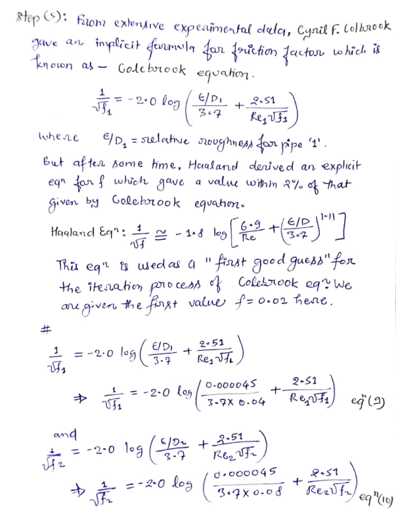
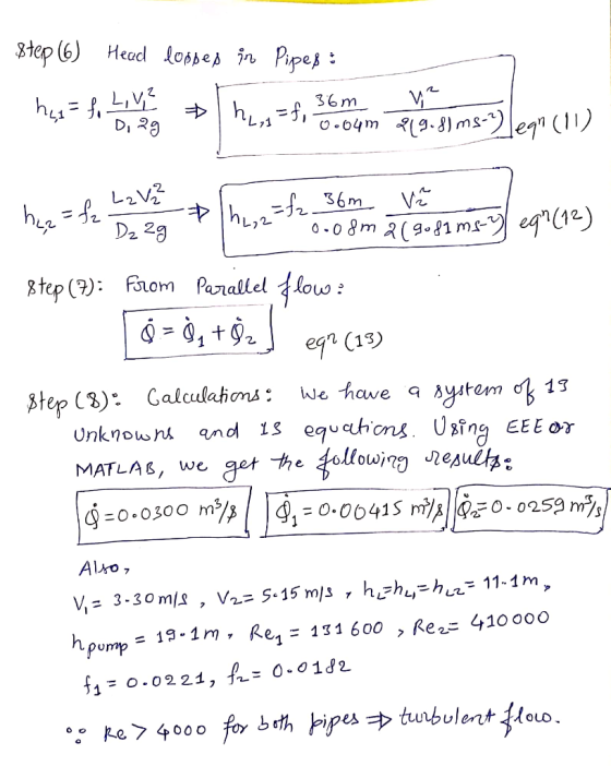
Two reservoirs are connected using the piping network shown in the figure. The pipes are commercial steel. Water is to be pumped using a pump (efficiency = 70%) that draws 8 kW of electric power from the mains. Ignore minor losses. Determine the flow rate through each pipe and the total flow between the reservoirs. Start with a friction factor of 0.02 for all pipes and use the Haaland equation to calculate updated friction factors. Ignore the length of the pipe between Reservoir 1 and the pump, pump and the junction, and the junction and Reservoir 2. Iterate until you have convergence or 3 iterations (whichever comes first) Look at Example 10-10 in the textbook to get an idea of how to solve this type of problem.
Homework Answers
Add Answer to:
Two reservoirs are connected using the piping network shown in the figure. The pipes are commerci...
[Problem 3] Two reservoirs are connected using the piping network shown in the figure. The pipes ...
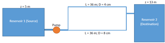
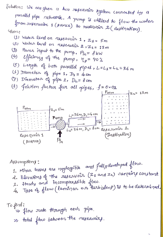
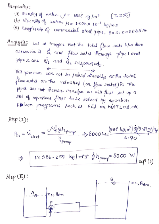
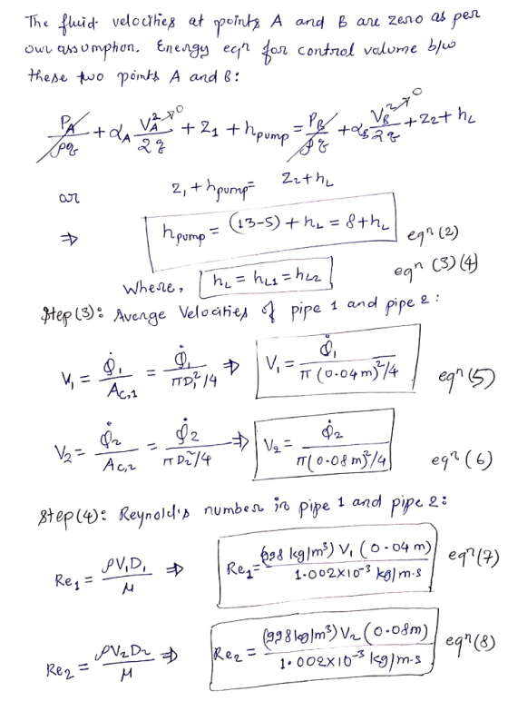
 [Problem 3] Two reservoirs are connected using the piping network shown in the figure. The pipes are commercial steel. water is to be pumped using a pump (efficiency = 70%) that draws 8 kw of electric power from the mains. Ignore minor losses. Determine the flow rate through each pipe and the total flow between the reservoirs. Start with a friction factor of 0.02 for all pipes and use the Haaland equation to calculate updated friction factors. Ignore the length...
4. Figure 2 shows two reservoirs which are connected by three pipes of different diameters. The...
 4. Figure 2 shows two reservoirs which are connected by three pipes of different diameters. The length and diameter of each pipe are given in Table 1. The flow rate in the pipeline is 55 Ls. The entrance and exit from the pipes are sharp and the change between the pipelines in the cross sections is sudden. Assume the friction factor, /for the pipes as 0.01. (a) Analyse all the head losses which occur, giving an expression for each. (7...
A pipe network is given below (Figure 2). All pipes are 1 km long, and 500...
 A pipe network is given below (Figure 2). All pipes are 1 km long, and 500 mm in diameter, with friction factor of 0 018 Determine the following. a) The value of Q (3) b) The correct flows in each pipe (using the Hardy-cross method) after the (17) first iteration [Hint: Assume Qo for pipe AB 105 L/s] c) The pressure heads at each node if the pressure head at reservoir A is 80 m. The elevation of each node...
The Figure below (Figure 3) shows a pipe system with a valve and two reservoirs
 QUESTION3 The Figure below (Figure 3) shows a pipe system with a valve and two reservoirs. A pump transports a constant flow rate of Q = 0.1 m3/s of water from reservoir A to reservoir B. At four sections the pipe has bends and the roughness of the pipe is ks = 1.5 mm. The pipe has a diameter D = 34 cm and a total length L = 500 m. The water level in reservoir B is Δh=4.67 m above...
Notre Dame University Faculty of Engineering Mechanical Engineering Dep Water flows through cast iron pipes and between the two tanks shown in Figure P4. The free sharp edge entrance. Bd by a dis...
 Notre Dame University Faculty of Engineering Mechanical Engineering Dep Water flows through cast iron pipes and between the two tanks shown in Figure P4. The free sharp edge entrance. Bd by a distance of 8 m. The water leaves Tank 1 through a contains a regular 90 threaded elbow and two unknown a regular 90° threaded elbow and a fully Branch pipeline 1 contains a regular 90 valves (valve 1 and valve 2). Branch pipeline 2 contains open gate valve....
(b) Water flows under gravity through a pipeline connecting two reservoirs as shown in Figure 2....
 (b) Water flows under gravity through a pipeline connecting two reservoirs as shown in Figure 2. The pipeline consists of 2 km of pipe diameter 400 mm and sand roughness equivalent 0.03 mm followed by an abrupt change to 3 km of 500 mm diameter pipe of sand roughness equivalent 0.08 mm. The pipe discharges as a free jet into a reservoir. The difference in elevation between the water surface of the upstream reservoir and the discharging jet is 21...
Water (density 998 kg/mº, dynamic viscosity 0.001 Pa s) is pumped between two reservoirs at a...
 Water (density 998 kg/mº, dynamic viscosity 0.001 Pa s) is pumped between two reservoirs at a volumetric flow rate of 0.006 m/s through a 120-m long pipe of 5 cm diameter. The roughness ratio of the pipe is a/d = 0.001. There are some fittings and valves in the pipe system, as shown in Figure Q1. The loss coefficients of the valves and fittings can be found in Table Q1. The Darcy friction factor can be found in the Moody...
Problem 3 A pipeline delivers water from Reservoir 1 to Reservoir 2 as shown in the following figure. The water levels at Reservoirs 1 and 2 are 50 ft and 20 ft, respectively. A globe valve is in...
 Problem 3 A pipeline delivers water from Reservoir 1 to Reservoir 2 as shown in the following figure. The water levels at Reservoirs 1 and 2 are 50 ft and 20 ft, respectively. A globe valve is installed in the pipeline with a minor head loss coefficient k 10. The pipe from Reservoir 1 to the globe valve is 1000 ft long and 6 inches in diameter. The pipe from the globe valve to Reservoir 2 is also 1000 ft...
 [Problem 3] Two reservoirs are connected using the piping network shown in the figure. The pipes are commercial steel. water is to be pumped using a pump (efficiency = 70%) that draws 8 kw of electric power from the mains. Ignore minor losses. Determine the flow rate through each pipe and the total flow between the reservoirs. Start with a friction factor of 0.02 for all pipes and use the Haaland equation to calculate updated friction factors. Ignore the length...
 4. Figure 2 shows two reservoirs which are connected by three pipes of different diameters. The length and diameter of each pipe are given in Table 1. The flow rate in the pipeline is 55 Ls. The entrance and exit from the pipes are sharp and the change between the pipelines in the cross sections is sudden. Assume the friction factor, /for the pipes as 0.01. (a) Analyse all the head losses which occur, giving an expression for each. (7...
 A pipe network is given below (Figure 2). All pipes are 1 km long, and 500 mm in diameter, with friction factor of 0 018 Determine the following. a) The value of Q (3) b) The correct flows in each pipe (using the Hardy-cross method) after the (17) first iteration [Hint: Assume Qo for pipe AB 105 L/s] c) The pressure heads at each node if the pressure head at reservoir A is 80 m. The elevation of each node...
 Notre Dame University Faculty of Engineering Mechanical Engineering Dep Water flows through cast iron pipes and between the two tanks shown in Figure P4. The free sharp edge entrance. Bd by a distance of 8 m. The water leaves Tank 1 through a contains a regular 90 threaded elbow and two unknown a regular 90° threaded elbow and a fully Branch pipeline 1 contains a regular 90 valves (valve 1 and valve 2). Branch pipeline 2 contains open gate valve....
 Notre Dame University Faculty of Engineering Mechanical Engineering Dep Water flows through cast iron pipes and between the two tanks shown in Figure P4. The free sharp edge entrance. Bd by a distance of 8 m. The water leaves Tank 1 through a contains a regular 90 threaded elbow and two unknown a regular 90° threaded elbow and a fully Branch pipeline 1 contains a regular 90 valves (valve 1 and valve 2). Branch pipeline 2 contains open gate valve....
 Notre Dame University Faculty of Engineering Mechanical Engineering Dep Water flows through cast iron pipes and between the two tanks shown in Figure P4. The free sharp edge entrance. Bd by a distance of 8 m. The water leaves Tank 1 through a contains a regular 90 threaded elbow and two unknown a regular 90° threaded elbow and a fully Branch pipeline 1 contains a regular 90 valves (valve 1 and valve 2). Branch pipeline 2 contains open gate valve....
 (b) Water flows under gravity through a pipeline connecting two reservoirs as shown in Figure 2. The pipeline consists of 2 km of pipe diameter 400 mm and sand roughness equivalent 0.03 mm followed by an abrupt change to 3 km of 500 mm diameter pipe of sand roughness equivalent 0.08 mm. The pipe discharges as a free jet into a reservoir. The difference in elevation between the water surface of the upstream reservoir and the discharging jet is 21...
 Water (density 998 kg/mº, dynamic viscosity 0.001 Pa s) is pumped between two reservoirs at a volumetric flow rate of 0.006 m/s through a 120-m long pipe of 5 cm diameter. The roughness ratio of the pipe is a/d = 0.001. There are some fittings and valves in the pipe system, as shown in Figure Q1. The loss coefficients of the valves and fittings can be found in Table Q1. The Darcy friction factor can be found in the Moody...
 Problem 3 A pipeline delivers water from Reservoir 1 to Reservoir 2 as shown in the following figure. The water levels at Reservoirs 1 and 2 are 50 ft and 20 ft, respectively. A globe valve is installed in the pipeline with a minor head loss coefficient k 10. The pipe from Reservoir 1 to the globe valve is 1000 ft long and 6 inches in diameter. The pipe from the globe valve to Reservoir 2 is also 1000 ft...
Most questions answered within 3 hours.
-
An empty test tube weighs 15.923 grams. Then,
MgCl2•6H2O is added into the test tube. After...
asked 12 minutes ago -
Please answer true or false. Words
cannot be changed or added in to make it true...
asked 11 minutes ago -
(a) A piston at 6.1 atm contains a gas that occupies a volume of
3.5 L....
asked 12 minutes ago -
Assume memory access is 10 units of time and disk access is
10000 units of time....
asked 30 minutes ago -
1. Are all good samples random?
2. Magazines often report surveys giving statistics such as “63%...
asked 52 minutes ago -
Under all the various types of market structures, firms
must eventually earn some economic profits for...
asked 38 minutes ago -
Consider the following fitness regime for a single locus trait
with two co-dominant alleles: w11 =...
asked 43 minutes ago -
A large cable company reports the following.
80% of its customers subscribe to its cable TV...
asked 58 minutes ago -
Please answer the question in brief.
Discuss the role of ERP in organizations. Are ERP tools...
asked 44 minutes ago -
Discuss the pros and cons of collaborative software such
as SameTime. Does it increase productivity? What...
asked 57 minutes ago -
Buying your in-laws a gift because it’s expected is
due to the ____________ motive of gift-giving....
asked 1 hour ago -
Calculate the expected value, the variance, and the standard
deviation of the given random variable X....
asked 1 hour ago