
Homework Answers


Add Answer to:
) An inductor is formed hy winding V tuns of a thin conducting wire into a circular f radius a. The inductor toop is in the plane with its center at the origin and connected to a resistor R. In t...
) An inductor is formed hy winding V tuns of a thin conducting wire into a...
 ) An inductor is formed hy winding V tuns of a thin conducting wire into a circular f radius a. The inductor toop is in the plane with its center at the origin and connected to a resistor R. In the presence of a loop as shown below around a non-magnetic material r- y magnetio field B ธิ 2094 + Z)sin(at) wb/m.. Teslas. where ω-angular frequency Derive and calculate the following parameters (a) Derive the magnetic flux linking a single...
Please show steps An inductor is formed by winding N turns of a thin conducting wire...
 Please show steps
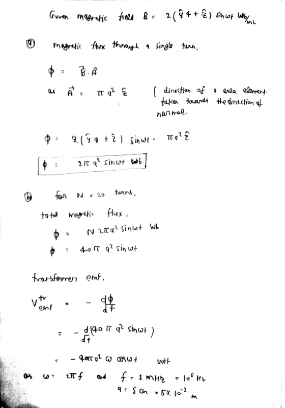
An inductor is formed by winding N turns of a thin conducting wire into a circular loop as shown below around a non-magnetic material of radius a. The inductor loop is in the r-y plane with its center at the origin and connected to a resistor R. In the presence of a magnetic fleld B 4. -2094+2) sin(ast) Wb/m2-Teslas, angular frequency where a N tums Derive and calculate the following parameters (a) Derive the magnetic flux linking...
Please show steps
An inductor is formed by winding N turns of a thin conducting wire into a circular loop as shown below around a non-magnetic material of radius a. The inductor loop is in the r-y plane with its center at the origin and connected to a resistor R. In the presence of a magnetic fleld B 4. -2094+2) sin(ast) Wb/m2-Teslas, angular frequency where a N tums Derive and calculate the following parameters (a) Derive the magnetic flux linking...
 ) An inductor is formed hy winding V tuns of a thin conducting wire into a circular f radius a. The inductor toop is in the plane with its center at the origin and connected to a resistor R. In the presence of a loop as shown below around a non-magnetic material r- y magnetio field B ธิ 2094 + Z)sin(at) wb/m.. Teslas. where ω-angular frequency Derive and calculate the following parameters (a) Derive the magnetic flux linking a single...
 Please show steps
An inductor is formed by winding N turns of a thin conducting wire into a circular loop as shown below around a non-magnetic material of radius a. The inductor loop is in the r-y plane with its center at the origin and connected to a resistor R. In the presence of a magnetic fleld B 4. -2094+2) sin(ast) Wb/m2-Teslas, angular frequency where a N tums Derive and calculate the following parameters (a) Derive the magnetic flux linking...
Please show steps
An inductor is formed by winding N turns of a thin conducting wire into a circular loop as shown below around a non-magnetic material of radius a. The inductor loop is in the r-y plane with its center at the origin and connected to a resistor R. In the presence of a magnetic fleld B 4. -2094+2) sin(ast) Wb/m2-Teslas, angular frequency where a N tums Derive and calculate the following parameters (a) Derive the magnetic flux linking...
Most questions answered within 3 hours.
-
A sample survey at a supermarket showed that 204 of 300 shoppers
regularly use cents-off coupons....
asked 5 seconds ago -
What is the HDI (Hydrogen Deficiency Index) for acetic acid? How
many sets of non-equivalent protons...
asked 50 seconds ago -
Disease Prevention and Health Promotion-Topic
What are the roles of both the state and federal government...
asked 5 minutes ago -
determine the following probabilites
a. for n= 3 and (pie)π = 0.16, what is P(X=0)?
b....
asked 8 minutes ago -
Why do men earn more money than women in America?
asked 18 minutes ago -
Sales of tablet computers at Ted Glickman's electronics store
in Washington, D.C., over the past 10...
asked 28 minutes ago -
Short essay question:
First, discuss the anatomical differences between Paleocene
pro-primates and Eocene eu-primates and explain...
asked 28 minutes ago -
Suppose we have a binomial experiment in which success is
defined to be a particular quality...
asked 49 minutes ago -
march the type of cellular control with the description: enzyme
induction and the enzyme repression. How...
asked 59 minutes ago -
Brief Exercise 5-09 (Part Level Submission)
The following information relates to Blue Spruce Corp. for the...
asked 59 minutes ago -
An unknown amount of a compound with a molecular mass of 284.04
g/mol is dissolved in...
asked 1 hour ago -
You are at rest at a stop sign. There is another stop sign that
is 100...
asked 1 hour ago