
Homework Answers
Add Answer to:
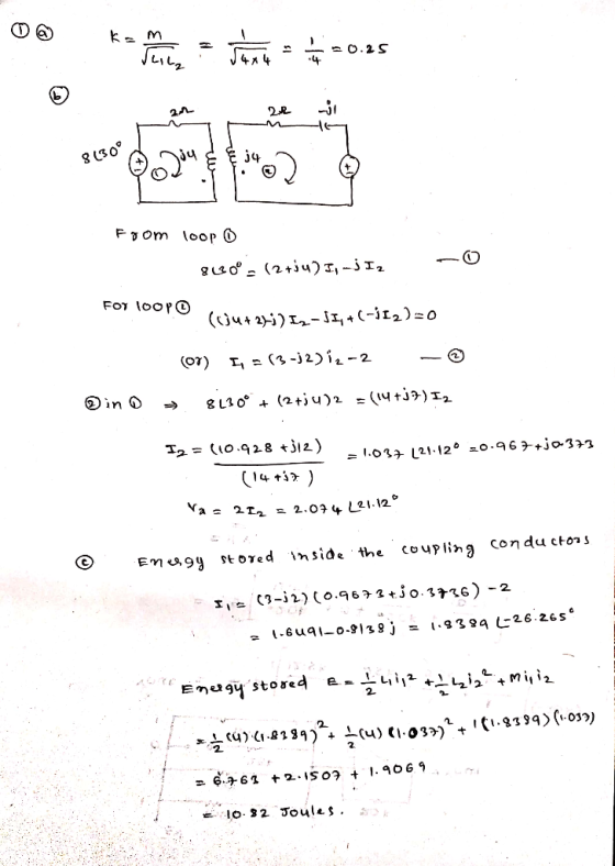
1. For the circuit shown in figure P-01, determine a. Coupling coefficient of coupled inductors! b. The voltage, Vx as shown in the circuit! C. Energy stored inside the coupled inductors! ML 2Ω Fi...
Palred Quiz) 3 For ideal transformer as shown in figure P.3, determine: a. The currents I1,...
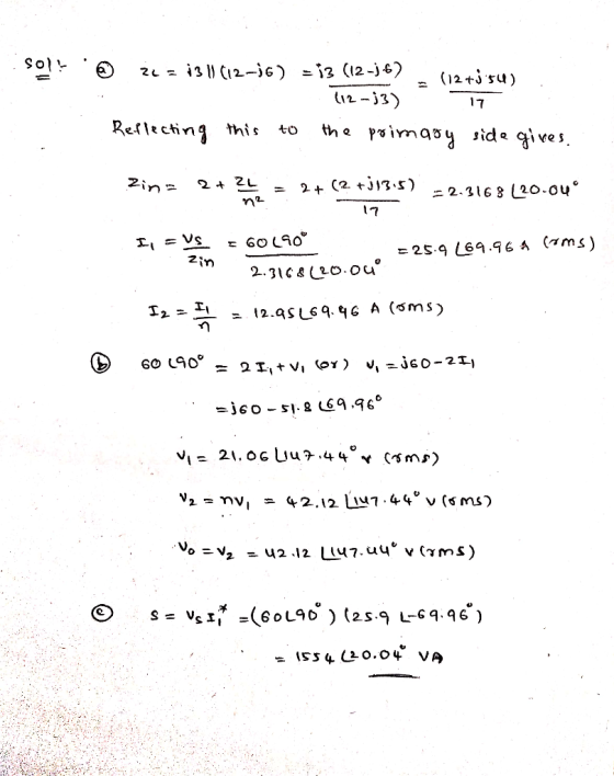
 Palred Quiz) 3 For ideal transformer as shown in figure P.3, determine: a. The currents I1, I2 and I3! b. The primary and secondary voltage Vu V, Vg and Va C. The complex power supplied by the source! d. The effective power dissipated by the load impedance, Zioad 812-20 Ω 1:3 18 Ω Zload 40200 v ( 45 Figure P.3 Ideal Transformer Circuit
2.120 pts] A schematic diagram of transformer is shown below. The closed path, l in the magnetic circuit in the Figure is traced by magnetic flux Ф. N,, N2, and 11, 12 are the numbers of turns and th...
 2.120 pts] A schematic diagram of transformer is shown below. The closed path, l in the magnetic circuit in the Figure is traced by magnetic flux Ф. N,, N2, and 11, 12 are the numbers of turns and the currents in the primary and secondary circuits, respectively. The permeability, and cross-section of ferromagnetic core is, u and A İl(r) (a) [6 pts] Draw an equivalent magnetic circuit with two magnetomotive force, Vmmfi, and Vmmf2, magnetic closed flux, 4, and magnetic...
1. (10 PT) A three-phase bridge rectifier circuit shown in the figure phase voltage of 220 volts rms. A load of 100 Ω is connected across is supplied by a rectifier. Both the primary and secondary...
 1. (10 PT) A three-phase bridge rectifier circuit shown in the figure phase voltage of 220 volts rms. A load of 100 Ω is connected across is supplied by a rectifier. Both the primary and secondary windings of transfor Assume the transformer has a turns ratio of unity mer are Y-connected a) 3 PTI On the top of voltage plot on next page indicate the diodes that will be conducting during different intervals of time. b) 17 PT] Plot the...
 Palred Quiz) 3 For ideal transformer as shown in figure P.3, determine: a. The currents I1, I2 and I3! b. The primary and secondary voltage Vu V, Vg and Va C. The complex power supplied by the source! d. The effective power dissipated by the load impedance, Zioad 812-20 Ω 1:3 18 Ω Zload 40200 v ( 45 Figure P.3 Ideal Transformer Circuit
 2.120 pts] A schematic diagram of transformer is shown below. The closed path, l in the magnetic circuit in the Figure is traced by magnetic flux Ф. N,, N2, and 11, 12 are the numbers of turns and the currents in the primary and secondary circuits, respectively. The permeability, and cross-section of ferromagnetic core is, u and A İl(r) (a) [6 pts] Draw an equivalent magnetic circuit with two magnetomotive force, Vmmfi, and Vmmf2, magnetic closed flux, 4, and magnetic...
 1. (10 PT) A three-phase bridge rectifier circuit shown in the figure phase voltage of 220 volts rms. A load of 100 Ω is connected across is supplied by a rectifier. Both the primary and secondary windings of transfor Assume the transformer has a turns ratio of unity mer are Y-connected a) 3 PTI On the top of voltage plot on next page indicate the diodes that will be conducting during different intervals of time. b) 17 PT] Plot the...
Most questions answered within 3 hours.
-
20% of all customers subscribe to phone service.
70% of all customers subscribe to internet service....
asked 1 minute from now -
Write a program to solve the Josephus problem, with the following
modification:
Sample Input:
./a.out n...
asked 2 hours ago -
At the start of a CD it is spinning at a rate of 525 rpm
(revolutions...
asked 3 hours ago -
4. Without doing any calculations, predict whether the observed
∆T would increase, decrease or remain the...
asked 4 hours ago -
Based on the range, which of the following sets of scores has
the greatest variability? 3,...
asked 5 hours ago -
Ripples in a pond travel at a velocity of 3 m/s with one peak
passing a...
asked 5 hours ago -
A man stands on the roof of a building of height 13.0 mm and
throws a...
asked 5 hours ago -
The extent to which assets are financed by borrowed funds and
other liabilities is indicated by:...
asked 6 hours ago -
Explain in detail
Germany is the fifth largest economy
explain what goods and services Germany specializes...
asked 6 hours ago -
The density of platinum is 21.45 g/mL. If a cube of platinum
with a mass of...
asked 6 hours ago -
Accounts Receivable
Sales
A/R Posting
Extended Sales Invoice
Packing Slip
Compare invoice to packing slip 2...
asked 7 hours ago -
Michaella, age 23, is a full-time law student and is claimed by
her parents as a...
asked 7 hours ago