
Homework Answers
Kindly upvote if it's helpful for you.
Add Answer to:
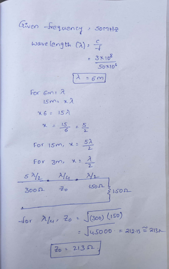
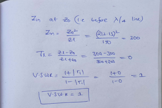
a. A 15-m length of 300 Ω lines must be connected to a 3-m length of 150 Ω lines that is terminated in a SO O resistor. Assuming all lines are lossless, find the vswR on the 300 Ω line. In order...
11.56 A 50 2 lossless transmission line that is 20 ml 120 + j220 Ω ossless transmission line that...
 USE QUARTER-WAVE METHOD
11.56 A 50 2 lossless transmission line that is 20 ml 120 + j220 Ω ossless transmission line that is 20 m long is terminated into a load. To perfectly match, what should be the length and location of a short-circuited stub line? Assume an operating frequency of 10 MHz. am
11.56 A 50 2 lossless transmission line that is 20 ml 120 + j220 Ω ossless transmission line that is 20 m long is terminated into...
USE QUARTER-WAVE METHOD
11.56 A 50 2 lossless transmission line that is 20 ml 120 + j220 Ω ossless transmission line that is 20 m long is terminated into a load. To perfectly match, what should be the length and location of a short-circuited stub line? Assume an operating frequency of 10 MHz. am
11.56 A 50 2 lossless transmission line that is 20 ml 120 + j220 Ω ossless transmission line that is 20 m long is terminated into...
Question 4 (a) The input impedance of a lossless air-core transmission line with characteristic impedance Ro. phase constant B and length I terminated in an impedance Z, is given by R,+Z, tan( i....
 Question 4 (a) The input impedance of a lossless air-core transmission line with characteristic impedance Ro. phase constant B and length I terminated in an impedance Z, is given by R,+Z, tan( i. Determine the length of an open circuit 50Ω line required to create a 0.1 nH inductor at a frequency of 10 GHz. (6 marks) ii. Determine the input impedance of the line in part () if the open circuit is changed to a short circuit. (3 marks)...
Note that there is a second valid solution. Problem #2) When an air-filled, slotted-line is terminated...
 Note that there is a second valid solution. Problem #2) When an air-filled, slotted-line is terminated with a "short-circuit", voltage minima are measured at positions of 10cm and 25cm on the line. When an unknown load" is connected to the line, the VSWR on the line is 2.4, and voltage minima are detected at 16cm and 31cm. Determine the impedance value of the load in rectangular form), the reflection coefficient of the load (in polar form), and the frequency of...
answer number 3 and 4 Problem 7. Transmission Lines The figure below shows a transmission line with a characteristic impedance Z,-50 Ω, connected to a single frequency generator with an internal i...
 answer number 3 and 4
Problem 7. Transmission Lines The figure below shows a transmission line with a characteristic impedance Z,-50 Ω, connected to a single frequency generator with an internal impedance R,-50 C (not shown), and terminated in a purely resistive load RL 50 2. At the frequency of the generator, the wavelength of the transmission line is λ = 2 m. At a distance dl-1.25 m away from the load, a shorted stub is connected via a tee....
answer number 3 and 4
Problem 7. Transmission Lines The figure below shows a transmission line with a characteristic impedance Z,-50 Ω, connected to a single frequency generator with an internal impedance R,-50 C (not shown), and terminated in a purely resistive load RL 50 2. At the frequency of the generator, the wavelength of the transmission line is λ = 2 m. At a distance dl-1.25 m away from the load, a shorted stub is connected via a tee....
A section of transmission line of 50 ohm characteristic impedance and 3x10^8 m/s propagation velocity carries...
A section of transmission line of 50 ohm characteristic impedance and 3x10^8 m/s propagation velocity carries simultaneously 300 MHz and 150 MHz signals. The line is terminated in a parallel connection of two sections of the same line, both sections terminated in 50 ohm resistance designated A and B. A 50 cm long open-circuited section is connected 50 cm from the connection to the driving line across the line terminated in resistance A. A 50 cm long short-circuited section (of...
elementR,-150 Ω is inserted in-between two lossless TEM A series lumped resisive in the figure below....
 elementR,-150 Ω is inserted in-between two lossless TEM A series lumped resisive in the figure below. The characteristic impedance of the first 2. ransm ol 100 Ω and the phase velocity is the speed of light (up transmission line (Tx-Line 1) SCctie impedance of the second transmission line (Tx-Line 2) section c = 3 x 10⁸ m/s). The character ond transmission line is terminated to the right so that there is no ission line sections as shown C3 x 10...
A generator is connected to a transmission line system that is shown below. The system consists o...
 please follow instruction and solve every task in detail, thank
you very much!
A generator is connected to a transmission line system that is shown below. The system consists of two transmission lines, each with a characteristic impedance of 75 [2], connected to a load impedance of 75 [2]. These two lines are then fed by a single main feed line having a characteristic impedance 75 [2], which is fed by the generator (not shown). It is desired to have...
please follow instruction and solve every task in detail, thank
you very much!
A generator is connected to a transmission line system that is shown below. The system consists of two transmission lines, each with a characteristic impedance of 75 [2], connected to a load impedance of 75 [2]. These two lines are then fed by a single main feed line having a characteristic impedance 75 [2], which is fed by the generator (not shown). It is desired to have...
Problem 3-15. Steady-State Conditions on a Transmission Line ine Che Chap. 3 3-11. A certain telephone...
 Problem 3-15.
Steady-State Conditions on a Transmission Line ine Che Chap. 3 3-11. A certain telephone cable has the following electrical characteristics: R = 40 /mi L = 1.1 mH/mi G = negligible C = 0.062 F/mi Loading coils are added which provide an additional inductance of 30 m / well as an additional resistance of 8 l/mi. Obtain the attenuation constan phase velocities at frequencies of 300 Hz and 3300 Hz. If the coil spacing is 1/6 at a...
Problem 3-15.
Steady-State Conditions on a Transmission Line ine Che Chap. 3 3-11. A certain telephone cable has the following electrical characteristics: R = 40 /mi L = 1.1 mH/mi G = negligible C = 0.062 F/mi Loading coils are added which provide an additional inductance of 30 m / well as an additional resistance of 8 l/mi. Obtain the attenuation constan phase velocities at frequencies of 300 Hz and 3300 Hz. If the coil spacing is 1/6 at a...
 USE QUARTER-WAVE METHOD
11.56 A 50 2 lossless transmission line that is 20 ml 120 + j220 Ω ossless transmission line that is 20 m long is terminated into a load. To perfectly match, what should be the length and location of a short-circuited stub line? Assume an operating frequency of 10 MHz. am
11.56 A 50 2 lossless transmission line that is 20 ml 120 + j220 Ω ossless transmission line that is 20 m long is terminated into...
USE QUARTER-WAVE METHOD
11.56 A 50 2 lossless transmission line that is 20 ml 120 + j220 Ω ossless transmission line that is 20 m long is terminated into a load. To perfectly match, what should be the length and location of a short-circuited stub line? Assume an operating frequency of 10 MHz. am
11.56 A 50 2 lossless transmission line that is 20 ml 120 + j220 Ω ossless transmission line that is 20 m long is terminated into...
 Question 4 (a) The input impedance of a lossless air-core transmission line with characteristic impedance Ro. phase constant B and length I terminated in an impedance Z, is given by R,+Z, tan( i. Determine the length of an open circuit 50Ω line required to create a 0.1 nH inductor at a frequency of 10 GHz. (6 marks) ii. Determine the input impedance of the line in part () if the open circuit is changed to a short circuit. (3 marks)...
 Note that there is a second valid solution. Problem #2) When an air-filled, slotted-line is terminated with a "short-circuit", voltage minima are measured at positions of 10cm and 25cm on the line. When an unknown load" is connected to the line, the VSWR on the line is 2.4, and voltage minima are detected at 16cm and 31cm. Determine the impedance value of the load in rectangular form), the reflection coefficient of the load (in polar form), and the frequency of...
 answer number 3 and 4
Problem 7. Transmission Lines The figure below shows a transmission line with a characteristic impedance Z,-50 Ω, connected to a single frequency generator with an internal impedance R,-50 C (not shown), and terminated in a purely resistive load RL 50 2. At the frequency of the generator, the wavelength of the transmission line is λ = 2 m. At a distance dl-1.25 m away from the load, a shorted stub is connected via a tee....
answer number 3 and 4
Problem 7. Transmission Lines The figure below shows a transmission line with a characteristic impedance Z,-50 Ω, connected to a single frequency generator with an internal impedance R,-50 C (not shown), and terminated in a purely resistive load RL 50 2. At the frequency of the generator, the wavelength of the transmission line is λ = 2 m. At a distance dl-1.25 m away from the load, a shorted stub is connected via a tee....
 elementR,-150 Ω is inserted in-between two lossless TEM A series lumped resisive in the figure below. The characteristic impedance of the first 2. ransm ol 100 Ω and the phase velocity is the speed of light (up transmission line (Tx-Line 1) SCctie impedance of the second transmission line (Tx-Line 2) section c = 3 x 10⁸ m/s). The character ond transmission line is terminated to the right so that there is no ission line sections as shown C3 x 10...
 please follow instruction and solve every task in detail, thank
you very much!
A generator is connected to a transmission line system that is shown below. The system consists of two transmission lines, each with a characteristic impedance of 75 [2], connected to a load impedance of 75 [2]. These two lines are then fed by a single main feed line having a characteristic impedance 75 [2], which is fed by the generator (not shown). It is desired to have...
please follow instruction and solve every task in detail, thank
you very much!
A generator is connected to a transmission line system that is shown below. The system consists of two transmission lines, each with a characteristic impedance of 75 [2], connected to a load impedance of 75 [2]. These two lines are then fed by a single main feed line having a characteristic impedance 75 [2], which is fed by the generator (not shown). It is desired to have...
 Problem 3-15.
Steady-State Conditions on a Transmission Line ine Che Chap. 3 3-11. A certain telephone cable has the following electrical characteristics: R = 40 /mi L = 1.1 mH/mi G = negligible C = 0.062 F/mi Loading coils are added which provide an additional inductance of 30 m / well as an additional resistance of 8 l/mi. Obtain the attenuation constan phase velocities at frequencies of 300 Hz and 3300 Hz. If the coil spacing is 1/6 at a...
Problem 3-15.
Steady-State Conditions on a Transmission Line ine Che Chap. 3 3-11. A certain telephone cable has the following electrical characteristics: R = 40 /mi L = 1.1 mH/mi G = negligible C = 0.062 F/mi Loading coils are added which provide an additional inductance of 30 m / well as an additional resistance of 8 l/mi. Obtain the attenuation constan phase velocities at frequencies of 300 Hz and 3300 Hz. If the coil spacing is 1/6 at a...
Most questions answered within 3 hours.
-
The free energy change for the following reaction at 25 °C, when
[Sn2+] = 1.17 M...
asked 1 hour ago -
An MNE is this kind of industry when competition in one country
is essentially independent of...
asked 2 hours ago -
. For this set of questions, determine what
proportion of a normal distribution is located betweeneach...
asked 3 hours ago -
A college student is employed as a door-to-door newspaper
salesman. Historical data suggests that the student...
asked 4 hours ago -
MATLAB HW 11 problem using Switch Case and Input commands
Write a script file that calculates...
asked 4 hours ago -
Considering gravitational time dilation, calculate the time that
passes in Earth’s surface while 1 hour passes...
asked 4 hours ago -
Minitab Problem: Take the Lake Hume June rainfall data and find
use the processes outlined in...
asked 5 hours ago -
X Company is trying to decide whether to continue using old
equipment to make Product A...
asked 5 hours ago -
IN PYTHON ONLY !! Program 2: Re-work
program #5 (WeeklyHours) from the previous assignment such that...
asked 6 hours ago -
The average length of time between arrivals at a turnpike
toll-booth is 26 seconds. What is...
asked 7 hours ago -
(a) A piston at 6.1 atm contains a gas that occupies a volume of
3.5 L....
asked 9 hours ago -
Please answer true or false. Words
cannot be changed or added in to make it true...
asked 9 hours ago