

2 D3 4 D2 2 DS Figure 3: Question 5
Homework Answers


Add Answer to:
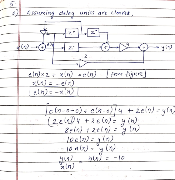
5. Consider the digital filter in Figure 3. (a) Assuming all delay units are cleared, find the transfer function for the filter (b) Write the difference equation for the filter. (c) Find the i...
Question 3 (30 marks) Consider the digital filter structure shown in the below figure: x[n yIn] 3 (a) Transform the giv...
 Question 3 (30 marks) Consider the digital filter structure shown in the below figure: x[n yIn] 3 (a) Transform the given block diagram to the transposed direct form II one. 2 (b) Determine the difference-equation representation of the system 4 (c) Find the transfer function for this causal filter and state the pole-zero pattern (d) Determine the impulse response of the system 2 (e) For what values of k is the system stable? (f) Determine yln if k 1 and...
b) Consider a simple difference equation ln)- x(n)+ax(n-D), where n7 is the input, y(n) is the output and D is a delay....
 b) Consider a simple difference equation ln)- x(n)+ax(n-D), where n7 is the input, y(n) is the output and D is a delay. Draw a block diagram of this filter and give a physical interpretation. Find its impulse response and transfer function. Calculate the zeros of the transfer function in terms of z Find the corresponding frequency response as well as the minimum and maximum values of the magnitude of the frequency response function.
b) Consider a simple difference equation ln)-...
b) Consider a simple difference equation ln)- x(n)+ax(n-D), where n7 is the input, y(n) is the output and D is a delay. Draw a block diagram of this filter and give a physical interpretation. Find its impulse response and transfer function. Calculate the zeros of the transfer function in terms of z Find the corresponding frequency response as well as the minimum and maximum values of the magnitude of the frequency response function.
b) Consider a simple difference equation ln)-...
1. By using an analog filter with a Butterworth response of order 3, design a digital IIR low pass filter with 3-db cutoff frequency 2c 0.6TT a) b) c) Evaluate the transfer function of the analog fil...
 1. By using an analog filter with a Butterworth response of order 3, design a digital IIR low pass filter with 3-db cutoff frequency 2c 0.6TT a) b) c) Evaluate the transfer function of the analog filter (10marks) Skecth the block diagram of transfer function (5 marks) Plot the magnitude response of the filters. (5marks)
1. By using an analog filter with a Butterworth response of order 3, design a digital IIR low pass filter with 3-db cutoff frequency 2c...
1. By using an analog filter with a Butterworth response of order 3, design a digital IIR low pass filter with 3-db cutoff frequency 2c 0.6TT a) b) c) Evaluate the transfer function of the analog filter (10marks) Skecth the block diagram of transfer function (5 marks) Plot the magnitude response of the filters. (5marks)
1. By using an analog filter with a Butterworth response of order 3, design a digital IIR low pass filter with 3-db cutoff frequency 2c...
a. b. c. d. An IIR filter has the difference equation: y'n Select the correct transfer function for this system...
 a.
b.
c.
d.
An IIR filter has the difference equation: y'n Select the correct transfer function for this system from the selections below. 2+1.2 No transfer function exists for this system. H(0.5+1.2Y(2)21 2+0.5 H(2)220.5z +1.2 An IIR filter has the transfer function: H(z) 22 +0.92-0.14 Select the correct impulse response for this system from the selections below hn 2(0.2)n-1un - 1] - 2(0.7)n-uln - 1 -hin] = 2(-0.2)"u[n]-2(-0.7)"u[n] hin] = 2(-0.2)"-iuln-11-2(-0.7)"-1 u[n-1] No impulse response exists for this system....
a.
b.
c.
d.
An IIR filter has the difference equation: y'n Select the correct transfer function for this system from the selections below. 2+1.2 No transfer function exists for this system. H(0.5+1.2Y(2)21 2+0.5 H(2)220.5z +1.2 An IIR filter has the transfer function: H(z) 22 +0.92-0.14 Select the correct impulse response for this system from the selections below hn 2(0.2)n-1un - 1] - 2(0.7)n-uln - 1 -hin] = 2(-0.2)"u[n]-2(-0.7)"u[n] hin] = 2(-0.2)"-iuln-11-2(-0.7)"-1 u[n-1] No impulse response exists for this system....
aliasing? A continuous-time system is given by the input/output differential equation 4. H(s) v(t) dy(t) dt dx(t) + 2 (+ x(t 2) dt (a) Determine its transfer function H(s)? (b) Determine its impulse...
 aliasing? A continuous-time system is given by the input/output differential equation 4. H(s) v(t) dy(t) dt dx(t) + 2 (+ x(t 2) dt (a) Determine its transfer function H(s)? (b) Determine its impulse response. (c) Determine its step response. (d) Is the stable? (a) Give two reasons why digital filters are favored over analog filters 5. (b) What is the main difference between IIR and FIR digital filters? (c) Give an example of a second order IIR filter and FIR...
Question 2 (10 points) Show all your work) inear time-invariant filter has the following transfer function: 1-3z H(z) 221리> 1+z-z 2 a) Is this filter an IIR or FIR? Explain. b) (1 point) What is...
 Question 2 (10 points) Show all your work) inear time-invariant filter has the following transfer function: 1-3z H(z) 221리> 1+z-z 2 a) Is this filter an IIR or FIR? Explain. b) (1 point) What is the order of this filter? (1 point) (1 point) 5 points) c) Is this filter stable? Explain. d) Determine the impulse response of the system. e) Determine the difference-equation description for the system. (2 points) nd order
Question 2 (10 points) Show all your work)...
Question 2 (10 points) Show all your work) inear time-invariant filter has the following transfer function: 1-3z H(z) 221리> 1+z-z 2 a) Is this filter an IIR or FIR? Explain. b) (1 point) What is the order of this filter? (1 point) (1 point) 5 points) c) Is this filter stable? Explain. d) Determine the impulse response of the system. e) Determine the difference-equation description for the system. (2 points) nd order
Question 2 (10 points) Show all your work)...
The circuit shown in Figure 2 is called a lead-lag filter. a) Find the transfer function...
 The circuit shown in Figure 2 is called a lead-lag filter. a) Find the transfer function Vols)/Vis). Assume an ideal operational amplifier. b) Determine the partial fraction expansion for Vols)/V(s) c) Determine Volt) and plot the results. Comment on the response of the filter 3. C1 R2 C2 iSin looot RI M(s) Figure 2: Lead-Lag Filter
are integers and 91 and 92 are 5. Consider the system diagram show in Fig. 2...
 are integers and 91 and 92 are 5. Consider the system diagram show in Fig. 2 for a digital filter. Assume N and M real-valued. (a) Use the diagram to write the difference equation that relates the input to the output. And use the difference equation to write the transfer function for the filter. No Matlab needed. (b) Assume N = 3, M = 5, 91 = 0.5 and 92 = 0.9. Write a Matlab function (call it "ece125filter”) that...
Please explain everything on how you got the slopes! Write out all KCL equations if necessary! Thank you! Problem 2: Find and plot the transfer function Vout vs. Vin for -5<Vin<5V, assuming FBV...
 Please explain everything on how you got the slopes! Write out
all KCL equations if necessary! Thank you!
Problem 2: Find and plot the transfer function Vout vs. Vin for -5<Vin<5V, assuming FBV 0. (20 pts) D1 2V Vout TVin D2
Problem 2: Find and plot the transfer function Vout vs. Vin for -5
Please explain everything on how you got the slopes! Write out
all KCL equations if necessary! Thank you!
Problem 2: Find and plot the transfer function Vout vs. Vin for -5<Vin<5V, assuming FBV 0. (20 pts) D1 2V Vout TVin D2
Problem 2: Find and plot the transfer function Vout vs. Vin for -5
Question 3 : (2.5 x 2 = 5 points) Consider the frequency response of a filter...
 Question 3 : (2.5 x 2 = 5 points) Consider the frequency response of a filter as shown in the figure below. a) Write the transfer function of the filter. b) Draw the circuit of the filter with proper component values. THA 0.707 0 10 f(Hz)
 Question 3 (30 marks) Consider the digital filter structure shown in the below figure: x[n yIn] 3 (a) Transform the given block diagram to the transposed direct form II one. 2 (b) Determine the difference-equation representation of the system 4 (c) Find the transfer function for this causal filter and state the pole-zero pattern (d) Determine the impulse response of the system 2 (e) For what values of k is the system stable? (f) Determine yln if k 1 and...
 b) Consider a simple difference equation ln)- x(n)+ax(n-D), where n7 is the input, y(n) is the output and D is a delay. Draw a block diagram of this filter and give a physical interpretation. Find its impulse response and transfer function. Calculate the zeros of the transfer function in terms of z Find the corresponding frequency response as well as the minimum and maximum values of the magnitude of the frequency response function.
b) Consider a simple difference equation ln)-...
b) Consider a simple difference equation ln)- x(n)+ax(n-D), where n7 is the input, y(n) is the output and D is a delay. Draw a block diagram of this filter and give a physical interpretation. Find its impulse response and transfer function. Calculate the zeros of the transfer function in terms of z Find the corresponding frequency response as well as the minimum and maximum values of the magnitude of the frequency response function.
b) Consider a simple difference equation ln)-...
 1. By using an analog filter with a Butterworth response of order 3, design a digital IIR low pass filter with 3-db cutoff frequency 2c 0.6TT a) b) c) Evaluate the transfer function of the analog filter (10marks) Skecth the block diagram of transfer function (5 marks) Plot the magnitude response of the filters. (5marks)
1. By using an analog filter with a Butterworth response of order 3, design a digital IIR low pass filter with 3-db cutoff frequency 2c...
1. By using an analog filter with a Butterworth response of order 3, design a digital IIR low pass filter with 3-db cutoff frequency 2c 0.6TT a) b) c) Evaluate the transfer function of the analog filter (10marks) Skecth the block diagram of transfer function (5 marks) Plot the magnitude response of the filters. (5marks)
1. By using an analog filter with a Butterworth response of order 3, design a digital IIR low pass filter with 3-db cutoff frequency 2c...
 a.
b.
c.
d.
An IIR filter has the difference equation: y'n Select the correct transfer function for this system from the selections below. 2+1.2 No transfer function exists for this system. H(0.5+1.2Y(2)21 2+0.5 H(2)220.5z +1.2 An IIR filter has the transfer function: H(z) 22 +0.92-0.14 Select the correct impulse response for this system from the selections below hn 2(0.2)n-1un - 1] - 2(0.7)n-uln - 1 -hin] = 2(-0.2)"u[n]-2(-0.7)"u[n] hin] = 2(-0.2)"-iuln-11-2(-0.7)"-1 u[n-1] No impulse response exists for this system....
a.
b.
c.
d.
An IIR filter has the difference equation: y'n Select the correct transfer function for this system from the selections below. 2+1.2 No transfer function exists for this system. H(0.5+1.2Y(2)21 2+0.5 H(2)220.5z +1.2 An IIR filter has the transfer function: H(z) 22 +0.92-0.14 Select the correct impulse response for this system from the selections below hn 2(0.2)n-1un - 1] - 2(0.7)n-uln - 1 -hin] = 2(-0.2)"u[n]-2(-0.7)"u[n] hin] = 2(-0.2)"-iuln-11-2(-0.7)"-1 u[n-1] No impulse response exists for this system....
 aliasing? A continuous-time system is given by the input/output differential equation 4. H(s) v(t) dy(t) dt dx(t) + 2 (+ x(t 2) dt (a) Determine its transfer function H(s)? (b) Determine its impulse response. (c) Determine its step response. (d) Is the stable? (a) Give two reasons why digital filters are favored over analog filters 5. (b) What is the main difference between IIR and FIR digital filters? (c) Give an example of a second order IIR filter and FIR...
 Question 2 (10 points) Show all your work) inear time-invariant filter has the following transfer function: 1-3z H(z) 221리> 1+z-z 2 a) Is this filter an IIR or FIR? Explain. b) (1 point) What is the order of this filter? (1 point) (1 point) 5 points) c) Is this filter stable? Explain. d) Determine the impulse response of the system. e) Determine the difference-equation description for the system. (2 points) nd order
Question 2 (10 points) Show all your work)...
Question 2 (10 points) Show all your work) inear time-invariant filter has the following transfer function: 1-3z H(z) 221리> 1+z-z 2 a) Is this filter an IIR or FIR? Explain. b) (1 point) What is the order of this filter? (1 point) (1 point) 5 points) c) Is this filter stable? Explain. d) Determine the impulse response of the system. e) Determine the difference-equation description for the system. (2 points) nd order
Question 2 (10 points) Show all your work)...
 The circuit shown in Figure 2 is called a lead-lag filter. a) Find the transfer function Vols)/Vis). Assume an ideal operational amplifier. b) Determine the partial fraction expansion for Vols)/V(s) c) Determine Volt) and plot the results. Comment on the response of the filter 3. C1 R2 C2 iSin looot RI M(s) Figure 2: Lead-Lag Filter
 are integers and 91 and 92 are 5. Consider the system diagram show in Fig. 2 for a digital filter. Assume N and M real-valued. (a) Use the diagram to write the difference equation that relates the input to the output. And use the difference equation to write the transfer function for the filter. No Matlab needed. (b) Assume N = 3, M = 5, 91 = 0.5 and 92 = 0.9. Write a Matlab function (call it "ece125filter”) that...
 Please explain everything on how you got the slopes! Write out
all KCL equations if necessary! Thank you!
Problem 2: Find and plot the transfer function Vout vs. Vin for -5<Vin<5V, assuming FBV 0. (20 pts) D1 2V Vout TVin D2
Problem 2: Find and plot the transfer function Vout vs. Vin for -5
Please explain everything on how you got the slopes! Write out
all KCL equations if necessary! Thank you!
Problem 2: Find and plot the transfer function Vout vs. Vin for -5<Vin<5V, assuming FBV 0. (20 pts) D1 2V Vout TVin D2
Problem 2: Find and plot the transfer function Vout vs. Vin for -5
 Question 3 : (2.5 x 2 = 5 points) Consider the frequency response of a filter as shown in the figure below. a) Write the transfer function of the filter. b) Draw the circuit of the filter with proper component values. THA 0.707 0 10 f(Hz)
Most questions answered within 3 hours.
-
Problem 16-02
Receivables Investment
Medwig Corporation has a DSO of 45 days. The company averages
$7,250...
asked 22 seconds ago -
Mr. Brown hired Lowe's Maintenance Services Limited to repair
and paint the exterior wall of his...
asked 59 seconds ago -
When might an index slow down the overall performance of the
database? Choose the best answer....
asked 6 minutes ago -
Due to a recession, expected inflation this year is only 2.25%.
However, the inflation rate in...
asked 7 minutes ago -
Write four functions: (IN PYTHON 3)
1) bound(l) - given a list of integers l, compute...
asked 9 minutes ago -
A quarterback throws a football. When the football leaves his
hand, it has a horizontal velocity...
asked 17 minutes ago -
he term "reproductive isolation mechanism" refers to
inability of a species to continue reproduction
specific areas...
asked 19 minutes ago -
In a certain binary-star system, each star has the same mass
which is 4.4 times of...
asked 24 minutes ago -
Use the model of the small open economy (Apply the small
open economy model of real...
asked 31 minutes ago -
The structure Car is declared as follows: struct Car { string
carMake; string carModel; int yearModel;...
asked 40 minutes ago -
Consider a transformer with 125 turns of wire in the primary
winding and 1475 turns of...
asked 41 minutes ago -
Let h be the depth below the surface of the ocean at which the
absolute pressure...
asked 42 minutes ago