![(a) A system has the impulse response, h[n], and is excited with the input signal, xIn], as shown below. Using either a mathe](http://img.homeworklib.com/images/eb6fd6f1-696a-445f-a4c7-6bc74650ffca.png?x-oss-process=image/resize,w_560)

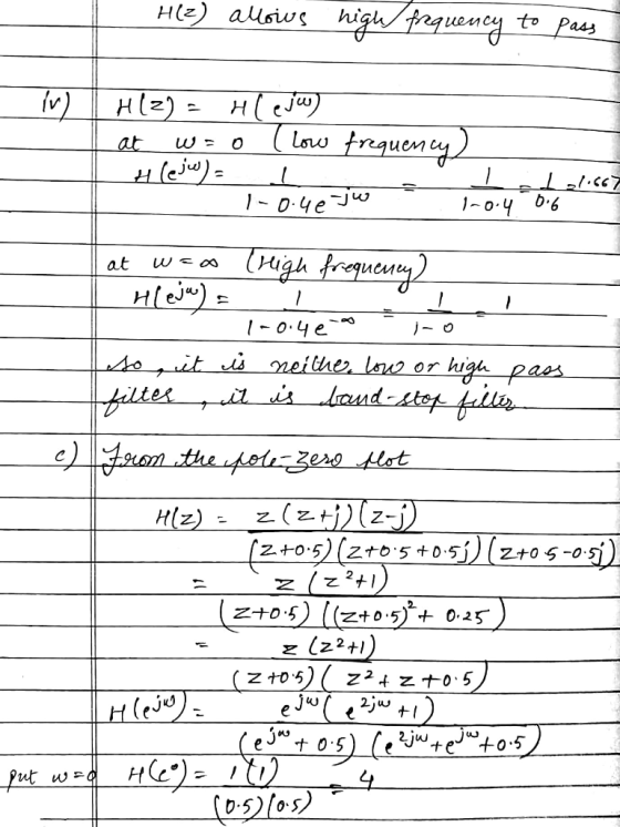
(c) A pole-zero map of a filter is given below. What type of frequency response characteristic would you expect from the filter (e.g. high-pass, low-pass, band-pass, or band-stop). Explain your answer? (use a diagram as an aid if necessary). [5 marks] Imaginary 0.5 Real 0.5 -0.5 -1
Homework Answers


Add Answer to:
(a) A system has the impulse response, h[n], and is excited with the input signal, xIn], as shown below. Using either a mathematical or a graphical convolution technique, determine the outp...
DSP Lab Exercise 9 Given below are the Impulse Response h(n), of the four main types of FIR Digit...
 DSP Lab Exercise 9 Given below are the Impulse Response h(n), of the four main types of FIR Digital filters. Use appropriate MATLAB expressions to find: a) System Response (H(z) b) Pole-zero diagram c) Amplitude Response d) Phase Response 1. FIR Low-Pass Digital Filter ,n= 0.1 |[d(n) + δ(n-I))-1 h(n) 0, otherwise 2. FIR High-Pass Digital Filter 0, otherwise 3. FIR Band-Pass Digital Filter 0, otherwise 4. FIR Band-Stop Digital Filter , n = 0,2 0, otherwise Note: Your final...
A linear time invariant system has an impulse response given by h[n] = 2(-0.5)" u[n] –...
 A linear time invariant system has an impulse response given by h[n] = 2(-0.5)" u[n] – 3(0.5)2º u[n] where u[n] is the unit step function. a) Find the z-domain transfer function H(2). b) Draw pole-zero plot of the system and indicate the region of convergence. c) is the system stable? Explain. d) is the system causal? Explain. e) Find the unit step response s[n] of the system, that is, the response to the unit step input. f) Provide a linear...
5 pts D Question 1 A system has the following impulse response: .2 Sample number, n From the choices below, select the frequency response of this system. H (eju)-e(1.5 ) (2 sin( 1.5ώ) +...
 5 pts D Question 1 A system has the following impulse response: .2 Sample number, n From the choices below, select the frequency response of this system. H (eju)-e(1.5 ) (2 sin( 1.5ώ) + 4 sin(0.δώ)) H (ee) = e-j(1.5e-5) (cos( 1.5 ) +2 cos(0.54)) @ H (ee)-e-n1.si) (sin( 1.54) t. 2 sin(0.δώ)) (sin(l.50) +4sin(0.0) H (ee)-e-j(1.5i) (2 cos( 1.5ώ) + 4 cos(0.5a)) H (efo)-e-n1.5u) (cos( 1.50) + 2 cos(0.50)) https://rmitinstructure.comcoursesy 5 pts DQuestion 2 A system has the following...
QUESTION 1 Characterise the following systems as being either causal on anticausal: yn)-ePyn-1)+u...
 QUESTION 1 Characterise the following systems as being either causal on anticausal: yn)-ePyn-1)+u/n), where u/h) is the unit step and B is an arbitrary constant (B>0), Take y-1)-0. Answer with either causal or 'anticausal only QUESTION 2 For the following system: yn) -yn-1Va -x(n), for a 0.9, find y(10), assuming y(n) - o, for ns -1.Hint: find a closed form for yin) and use it to find the required output sample. (xin)-1 for n>-0) QUESTION 3 A filter has the...
a) List the relative attributes of using digital processing techniques compared to traditional analogue hardware for signal processing. [5 marks] b) Sketch a z-plane diagram including the unit ci...
 a) List the relative attributes of using digital processing techniques compared to traditional analogue hardware for signal processing. [5 marks] b) Sketch a z-plane diagram including the unit circle. You have four Poles and two Zeros that you can place on the z-plane diagram. Place them in a position which would provide a digital band-stop filter characteristic with the 'notch' at a n/2 Justify your placement of the poles and zeros. 5 marks] c) The z-plane pole-zero plots of two...
(1) For the impulse response (h(t)) and input signal (x(t)) of an LTI system shown below,...
 (1) For the impulse response (h(t)) and input signal (x(t)) of an LTI system shown below, find and plot the output response (y(t)) by integrating the convolution analytically h(t) x(t) t (s)
Question 4 (a) Find the DFT of the series x[n)-(0.2,1,1,0.2), and sketch the magnitude of the resulting spectral components [10 marks] (b) For a discrete impulse response, h[n], that is symmetric...
 Question 4 (a) Find the DFT of the series x[n)-(0.2,1,1,0.2), and sketch the magnitude of the resulting spectral components [10 marks] (b) For a discrete impulse response, h[n], that is symmetric about the origin, the spectral coefficients of the signal, H(k), can be obtained by use of the DFT He- H(k)- H-(N-1)/2 Conversely, if the spectral coefficients, H(k), are known (and are even and symmetrical about k-0), the original signal, h[n], can be reconstituted using the inverse DFT 1 (N-D/2...
A system has an input, x(t) and an impulse response, h(t). Using the convolution integral, find...
 A system has an input, x(t) and an impulse response, h(t). Using
the convolution integral,
find and plot the system output, y(t), for the combination given
below.
x(t) is P3.2(e) and h(t) is P3.2(f).
1/2 cycle of 2 cos at -2. (e)
A system has an input, x(t) and an impulse response, h(t). Using
the convolution integral,
find and plot the system output, y(t), for the combination given
below.
x(t) is P3.2(e) and h(t) is P3.2(f).
1/2 cycle of 2 cos at -2. (e)
1. An LTI system has an impulse response h[n] for which thez transform is a. Plot...
 1. An LTI system has an impulse response h[n] for which thez transform is a. Plot the pole-zero pattern for H(z). b. Using the fact that signals of the form z are eigenfunctions of LTI systems, determine the system output for all n if the input x [n] is given by 72 I3(2)
Consider the LTI system described by the following impulse response: (a) h(n) = 2(0.5)n u(n). Determine:...
Consider the LTI system described by the following impulse response: (a) h(n) = 2(0.5)n u(n). Determine: (i) The system function representation; (ii) the difference-equation representation (Note: this is just terminology that refers to expressing the input and output time-domain signals in the form of an equation. E.g., what we did when we went over the equations for block diagrams); (iii) The pole-zero plot, sketched by hand; and (iv) the output y(n) if the input is x(n) = (0.25)n u(n) [10...
 DSP Lab Exercise 9 Given below are the Impulse Response h(n), of the four main types of FIR Digital filters. Use appropriate MATLAB expressions to find: a) System Response (H(z) b) Pole-zero diagram c) Amplitude Response d) Phase Response 1. FIR Low-Pass Digital Filter ,n= 0.1 |[d(n) + δ(n-I))-1 h(n) 0, otherwise 2. FIR High-Pass Digital Filter 0, otherwise 3. FIR Band-Pass Digital Filter 0, otherwise 4. FIR Band-Stop Digital Filter , n = 0,2 0, otherwise Note: Your final...
 A linear time invariant system has an impulse response given by h[n] = 2(-0.5)" u[n] – 3(0.5)2º u[n] where u[n] is the unit step function. a) Find the z-domain transfer function H(2). b) Draw pole-zero plot of the system and indicate the region of convergence. c) is the system stable? Explain. d) is the system causal? Explain. e) Find the unit step response s[n] of the system, that is, the response to the unit step input. f) Provide a linear...
 5 pts D Question 1 A system has the following impulse response: .2 Sample number, n From the choices below, select the frequency response of this system. H (eju)-e(1.5 ) (2 sin( 1.5ώ) + 4 sin(0.δώ)) H (ee) = e-j(1.5e-5) (cos( 1.5 ) +2 cos(0.54)) @ H (ee)-e-n1.si) (sin( 1.54) t. 2 sin(0.δώ)) (sin(l.50) +4sin(0.0) H (ee)-e-j(1.5i) (2 cos( 1.5ώ) + 4 cos(0.5a)) H (efo)-e-n1.5u) (cos( 1.50) + 2 cos(0.50)) https://rmitinstructure.comcoursesy 5 pts DQuestion 2 A system has the following...
 QUESTION 1 Characterise the following systems as being either causal on anticausal: yn)-ePyn-1)+u/n), where u/h) is the unit step and B is an arbitrary constant (B>0), Take y-1)-0. Answer with either causal or 'anticausal only QUESTION 2 For the following system: yn) -yn-1Va -x(n), for a 0.9, find y(10), assuming y(n) - o, for ns -1.Hint: find a closed form for yin) and use it to find the required output sample. (xin)-1 for n>-0) QUESTION 3 A filter has the...
 a) List the relative attributes of using digital processing techniques compared to traditional analogue hardware for signal processing. [5 marks] b) Sketch a z-plane diagram including the unit circle. You have four Poles and two Zeros that you can place on the z-plane diagram. Place them in a position which would provide a digital band-stop filter characteristic with the 'notch' at a n/2 Justify your placement of the poles and zeros. 5 marks] c) The z-plane pole-zero plots of two...
 (1) For the impulse response (h(t)) and input signal (x(t)) of an LTI system shown below, find and plot the output response (y(t)) by integrating the convolution analytically h(t) x(t) t (s)
 Question 4 (a) Find the DFT of the series x[n)-(0.2,1,1,0.2), and sketch the magnitude of the resulting spectral components [10 marks] (b) For a discrete impulse response, h[n], that is symmetric about the origin, the spectral coefficients of the signal, H(k), can be obtained by use of the DFT He- H(k)- H-(N-1)/2 Conversely, if the spectral coefficients, H(k), are known (and are even and symmetrical about k-0), the original signal, h[n], can be reconstituted using the inverse DFT 1 (N-D/2...
 A system has an input, x(t) and an impulse response, h(t). Using
the convolution integral,
find and plot the system output, y(t), for the combination given
below.
x(t) is P3.2(e) and h(t) is P3.2(f).
1/2 cycle of 2 cos at -2. (e)
A system has an input, x(t) and an impulse response, h(t). Using
the convolution integral,
find and plot the system output, y(t), for the combination given
below.
x(t) is P3.2(e) and h(t) is P3.2(f).
1/2 cycle of 2 cos at -2. (e)
 1. An LTI system has an impulse response h[n] for which thez transform is a. Plot the pole-zero pattern for H(z). b. Using the fact that signals of the form z are eigenfunctions of LTI systems, determine the system output for all n if the input x [n] is given by 72 I3(2)
Most questions answered within 3 hours.
-
1,1-dimethylcyclorohexane reacts with single bromine atom
asked 7 minutes ago -
The completed Lewis structure of CO2 contains a total
of 0,1,2,3,4,5,6,7,8 covalent bonds
and 0,1,2,3,4,5,6,7,8 lone pairs.
NOTE:...
asked 13 minutes ago -
A 0.0510 M solution of an organic acid has an
[H+] of 7.50×10⁻⁴M .
What is...
asked 10 minutes ago -
what is the profit-maximizing output condition that a
monopolistically competitive firm must satisfy? a) price charged...
asked 15 minutes ago -
Consider the set of ordered pairs shown below. Assuming that the
regression equation is y=3.513+0.429x and...
asked 36 minutes ago -
1. (A) Write two
structural (constitutional)
isomers of C4H8F2?
Please show all of
the
asked 38 minutes ago -
Objective: Practice converting a Boolean logic
expression into it’s truth table and to show the implementation...
asked 35 minutes ago -
1) Name the three holes located in the greater wing of the
sphenoid bone in order...
asked 39 minutes ago -
For the following reaction set-up, which type of hydrocarbon
product would form? 1,4-hexadiene + two Cl2...
asked 41 minutes ago -
Consider the following method that is intended to determine if
the double values d1 and d2...
asked 54 minutes ago -
could someone please post clear drawings of the three structures
in the equilibrium mixture of D-glucose...
asked 1 hour ago -
Using the Properties of Order show that 5n5 +
4n4 + 6n3 + 2n2+ n +...
asked 1 hour ago