Counterbore R13 3 20 4 Hoies 88 equi-spaced 20 60 2 50 020 1010 R13 04 2 45 57 2 45 04 3 5 25 24
Homework Answers

if you want any modifications please comment bellow
please Thumbs up!
Add Answer to:
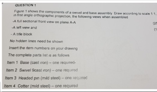
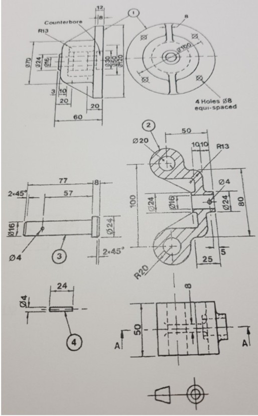
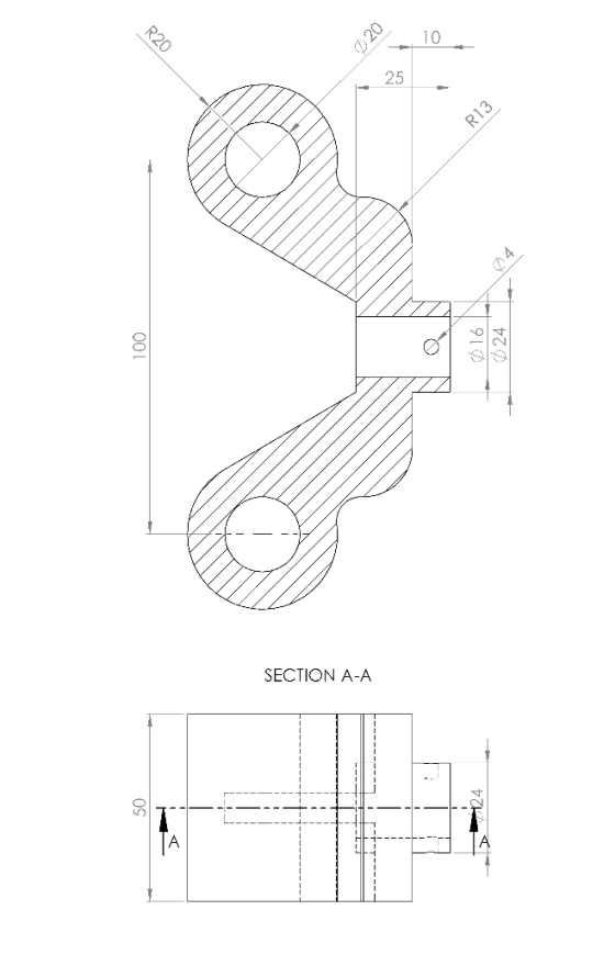
QUESTION 1 Figure 1 shows the components of a swivel and base assembly Draw according to scale 1 1, in first angle orthographic projection, the following views when assembled -A full sectional...
MAY/JUNE 2017 QUESTION 1 Figure 1 shows the components of an IDLER PULLEY Draw according to scale 1 1, ın first angle orthographic projection, the following views when assembled - A full secti...
 MAY/JUNE 2017 QUESTION 1 Figure 1 shows the components of an IDLER PULLEY Draw according to scale 1 1, ın first angle orthographic projection, the following views when assembled - A full sectional front view (According to component 1 section) - A left view (24) (14) - And a title block Insert item numbers in the assembly drawing The complete part list is as follows | DESCRIPTION | MATERIAL QUANTITY BODY PULLEY PIN SHAFT BUSH HEXAGONAL NUT I M S...
Figure 1 shows a ROLLER SUPPORT ASSEMBLY that contains several parts. including standard components. The specifications for all components are given in Table 1 Table 1: Components of roller su...
 Figure 1 shows a ROLLER SUPPORT ASSEMBLY that contains several parts. including standard components. The specifications for all components are given in Table 1 Table 1: Components of roller support assembly PART I NAME MATERIAL DETAIL DRAWING REQUIRED NO BASF PLATE 1010 STFF CAST IRON NO 2 BRACKET NO BUSHING BRASS NO SHAFT YES ELL ROILER SCREW M18 x 2.5 25 MIN LG FULL THD GREASE FITTING MB X 010 SIEE YES 6 1020 SIEEL NO NO 020 SIEEL Create...
 MAY/JUNE 2017 QUESTION 1 Figure 1 shows the components of an IDLER PULLEY Draw according to scale 1 1, ın first angle orthographic projection, the following views when assembled - A full sectional front view (According to component 1 section) - A left view (24) (14) - And a title block Insert item numbers in the assembly drawing The complete part list is as follows | DESCRIPTION | MATERIAL QUANTITY BODY PULLEY PIN SHAFT BUSH HEXAGONAL NUT I M S...
 Figure 1 shows a ROLLER SUPPORT ASSEMBLY that contains several parts. including standard components. The specifications for all components are given in Table 1 Table 1: Components of roller support assembly PART I NAME MATERIAL DETAIL DRAWING REQUIRED NO BASF PLATE 1010 STFF CAST IRON NO 2 BRACKET NO BUSHING BRASS NO SHAFT YES ELL ROILER SCREW M18 x 2.5 25 MIN LG FULL THD GREASE FITTING MB X 010 SIEE YES 6 1020 SIEEL NO NO 020 SIEEL Create...
Most questions answered within 3 hours.
-
Write the ionic equations for the first stage of salts
hydrolysis.
Anion, Cation?
Na2S
NiSO4
K2SO4...
asked 41 minutes ago -
suppose there is a normally distributed population with a mean of
250 and a standard deviation...
asked 1 hour ago -
Question Three
Suppose you as project manager are using the Waterfall
development methodology on a large...
asked 2 hours ago -
Which statement is not true about welfare in Canada?
A.Benefits typically vary based on one's ability...
asked 2 hours ago -
Please help me with FLOWCHART and UML diagram for class,
thank you!
#include <iostream>
#include <fstream>...
asked 3 hours ago -
3. Describe the “logic circuit” of the Lac operon. Which
proteins are bound or not to...
asked 3 hours ago -
Ayesha’s adjusted gross income is $60,000 in 2019. She donated a
piece of artwork with a...
asked 3 hours ago -
For Dijkstra’s shortest path algorithm:
a. Give the Big-O time for Dijkstra’s shortest path algorithm
and...
asked 4 hours ago -
Phosphorus violates the 'octet rule' in biological molecules,
forming more covalent bonds than expected based on...
asked 4 hours ago -
A 1.3 eV electron has a 10-4 probability of tunneling
through a 2.4 eV potential barrier....
asked 4 hours ago -
What is the one ingredient that is common to being successful
with all stakeholders?
profit
trust...
asked 4 hours ago -
Write an assembly language 32 bit program that reads in lines of
text by a .txt...
asked 4 hours ago