


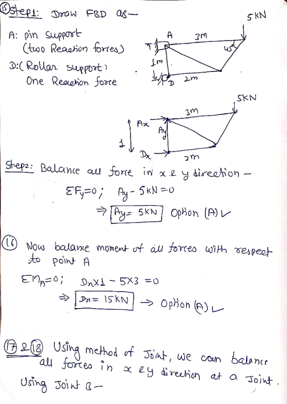
Question 16 For the truss shown in the figure below, determine the horizontal reaction force at support D: 5 kN 45° 1 m 2 m + 15 kN - 12.5 kN 0 kN +5 kN
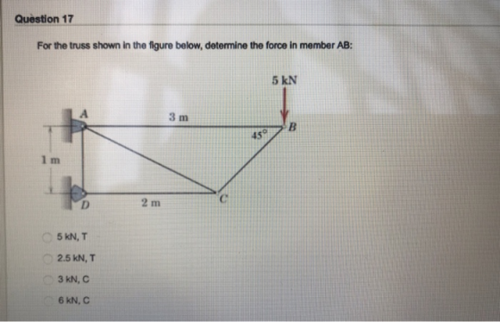
Question 17 For the truss shown in the figure below, determine the force in member AB: 5 kN 3 m 45 2 m 5 kN, T 2.5 kN, T 3kN, C 6 KN, C
Question 18 For the truss shown in the figure below, determine the force in member BC: 5 kN 3 m 45 1 m 2 m 11.8 KN, C 4.5 kN, T 7.07 kN, C 8.02 KN, T
Homework Answers
 Thanks
Add Answer to:
Question 15 For the truss shown in the figure below, determine the vertical reaction force at support A 5 kN 3 m 45 1 m 2 m +5 KN + 4.3 kN -3 kN -5 kN Question 16 For the truss shown in the fi...
6 m 2.5 m Question 3 The simple truss shown in the Figure is to be...
 6 m 2.5 m Question 3 The simple truss shown in the Figure is to be analyzed. If the angle of support surface at C can be varied from 0° (vertical) to 90° (horizontal), plot the force in member BC as a function of over this range. For your plot note any unusual conditions. For what value of e, if any, is the force in member BC zero? If member BC is designed to fail at a load of 10000...
QUESTION 2 For the below loaded truss, P1-20 kN, P2 30 kN, P3-40 kN. 3 m...
 QUESTION 2 For the below loaded truss, P1-20 kN, P2 30 kN, P3-40 kN. 3 m B 12 m--2 m--2 m--2 m--2 m-1-2 m- P Choose the best answer for the force in member KC in kN if the vertical reaction Gy 33.33 kN. State d the member is in tension (T) or compression (C) 12.67 (C) a.67 (C) 6.6 (D 12.67 ( For the below loaded truss, P1-20 kN, P2 30 KN, P3-40 kN. H 3 m D F...
Consider the truss (Figure 1). Suppose that F = 11 kN . Determine the force in...
 Consider the truss (Figure 1). Suppose that F = 11 kN .
Determine the force in member BC, HC, and HG.
Figure 1 of 1 6 kN 9 kN 6 kN Imm Imm 5 m1.5 m 1.5 m1.5 m
Consider the truss (Figure 1). Suppose that F = 11 kN .
Determine the force in member BC, HC, and HG.
Figure 1 of 1 6 kN 9 kN 6 kN Imm Imm 5 m1.5 m 1.5 m1.5 m
In the truss shown in the figure: 1. Determine the support reactions at supports A and...
 In the truss shown in the figure: 1. Determine the support reactions at supports A and F. (10 points) 2. Determine the force in members BC, IC, and IH of the truss using method of joints. Explain and justify if the members are in tension or compression. (20 points) 3. Draw FBD for each step of 1 and 2. (10 points) 60KN 40 kN -2 m -2 m -2 m E D 1.5 m F с O -30 kN H...
SAN4701 JAN/FEB 2015 QUESTION 1 The truss shown in Figure 1 is hinged at C, B and D It is acted upon at node A by a ver...
 SAN4701 JAN/FEB 2015 QUESTION 1 The truss shown in Figure 1 is hinged at C, B and D It is acted upon at node A by a vertically downward force of 3 kN and a honzontal force of 5 kN as shown in Figure 1 Use the method of strffness matrix and analyse for the following (a) Displacement at node A (16) (b) Reaction at the supports (c) Member forces (15) EA 300 x 103 kN and is constant for...
Po 13.6 kN Value Units Figure Part kN Part A Determine the force in member BC of the truss and ...
 Po 13.6 kN Value Units Figure Part kN Part A Determine the force in member BC of the truss and state if this member is in tension or compression. Express your answer to three significant figures and include the appropriate units. Enter negative value in the case of Consider the truss showm in (Figure 1). Set P1-6 kN, compression and positive value in the case of tension Figure 1 of 1 Poc 15.6 kN Submit X Incorrect; Try Again; 3...
Consider the truss shown in (Figure 1). Suppose that F = 3.5 kN. Assume all members...
 Consider the truss shown in (Figure 1). Suppose that F = 3.5 kN.
Assume all members are pin connected.
Part A: Determine the force in member GC of the truss and state
if the member is in tension or compression.
Part B: Determine the force in member BC of the truss and state
if the member is in tension or compression.
Part C: Determine the force in member GF of the truss and state
if the member is in tension...
Consider the truss shown in (Figure 1). Suppose that F = 3.5 kN.
Assume all members are pin connected.
Part A: Determine the force in member GC of the truss and state
if the member is in tension or compression.
Part B: Determine the force in member BC of the truss and state
if the member is in tension or compression.
Part C: Determine the force in member GF of the truss and state
if the member is in tension...
4. TRUSS Determine the force in each member of the truss shown below. Also, state whether...
 4. TRUSS Determine the force in each member of the truss shown below. Also, state whether each member is in tension or compression. There is a pin at A and a rocker at C. 45 KN 35 kN 12 m ....... 10 m -........................... 10 m -.......... 20 KN
Determine the forces in each member of the truss shown in figure 11. Above. 120 KN...
 Determine the forces in each member of the truss shown in figure
11. Above.
120 KN 120 KN 4 m 120 KN H E F 60 KN 60 KN 4 m 40 KN 40 KN A B D 8 m +2 m|-3 m-3m|3m|3m|2m1 8 m Figure 11: A truss. GROUP 2B QUESTION 12: You have just graduated from CBU as a civil engineer. A water utility company employs you. During maintenance, in turning the water pump steadily, you exert a...
Determine the forces in each member of the truss shown in figure
11. Above.
120 KN 120 KN 4 m 120 KN H E F 60 KN 60 KN 4 m 40 KN 40 KN A B D 8 m +2 m|-3 m-3m|3m|3m|2m1 8 m Figure 11: A truss. GROUP 2B QUESTION 12: You have just graduated from CBU as a civil engineer. A water utility company employs you. During maintenance, in turning the water pump steadily, you exert a...
Estimate the redundant force in the truss member BC as shown in the following FIGURE. The...
 Estimate the redundant force in the truss member BC as shown in the following FIGURE. The truss is subjected to a vertical load P as 50 kN. Members AB, AC, CD, and BD are 5 m long. The cross-sectional area of all members is constant. The support at A is the pin support and the support at B is the roller support. P = 50 kN Ан, B Av Ву
 6 m 2.5 m Question 3 The simple truss shown in the Figure is to be analyzed. If the angle of support surface at C can be varied from 0° (vertical) to 90° (horizontal), plot the force in member BC as a function of over this range. For your plot note any unusual conditions. For what value of e, if any, is the force in member BC zero? If member BC is designed to fail at a load of 10000...
 QUESTION 2 For the below loaded truss, P1-20 kN, P2 30 kN, P3-40 kN. 3 m B 12 m--2 m--2 m--2 m--2 m-1-2 m- P Choose the best answer for the force in member KC in kN if the vertical reaction Gy 33.33 kN. State d the member is in tension (T) or compression (C) 12.67 (C) a.67 (C) 6.6 (D 12.67 ( For the below loaded truss, P1-20 kN, P2 30 KN, P3-40 kN. H 3 m D F...
 Consider the truss (Figure 1). Suppose that F = 11 kN .
Determine the force in member BC, HC, and HG.
Figure 1 of 1 6 kN 9 kN 6 kN Imm Imm 5 m1.5 m 1.5 m1.5 m
Consider the truss (Figure 1). Suppose that F = 11 kN .
Determine the force in member BC, HC, and HG.
Figure 1 of 1 6 kN 9 kN 6 kN Imm Imm 5 m1.5 m 1.5 m1.5 m
 In the truss shown in the figure: 1. Determine the support reactions at supports A and F. (10 points) 2. Determine the force in members BC, IC, and IH of the truss using method of joints. Explain and justify if the members are in tension or compression. (20 points) 3. Draw FBD for each step of 1 and 2. (10 points) 60KN 40 kN -2 m -2 m -2 m E D 1.5 m F с O -30 kN H...
 SAN4701 JAN/FEB 2015 QUESTION 1 The truss shown in Figure 1 is hinged at C, B and D It is acted upon at node A by a vertically downward force of 3 kN and a honzontal force of 5 kN as shown in Figure 1 Use the method of strffness matrix and analyse for the following (a) Displacement at node A (16) (b) Reaction at the supports (c) Member forces (15) EA 300 x 103 kN and is constant for...
 Po 13.6 kN Value Units Figure Part kN Part A Determine the force in member BC of the truss and state if this member is in tension or compression. Express your answer to three significant figures and include the appropriate units. Enter negative value in the case of Consider the truss showm in (Figure 1). Set P1-6 kN, compression and positive value in the case of tension Figure 1 of 1 Poc 15.6 kN Submit X Incorrect; Try Again; 3...
 Consider the truss shown in (Figure 1). Suppose that F = 3.5 kN.
Assume all members are pin connected.
Part A: Determine the force in member GC of the truss and state
if the member is in tension or compression.
Part B: Determine the force in member BC of the truss and state
if the member is in tension or compression.
Part C: Determine the force in member GF of the truss and state
if the member is in tension...
Consider the truss shown in (Figure 1). Suppose that F = 3.5 kN.
Assume all members are pin connected.
Part A: Determine the force in member GC of the truss and state
if the member is in tension or compression.
Part B: Determine the force in member BC of the truss and state
if the member is in tension or compression.
Part C: Determine the force in member GF of the truss and state
if the member is in tension...
 4. TRUSS Determine the force in each member of the truss shown below. Also, state whether each member is in tension or compression. There is a pin at A and a rocker at C. 45 KN 35 kN 12 m ....... 10 m -........................... 10 m -.......... 20 KN
 Determine the forces in each member of the truss shown in figure
11. Above.
120 KN 120 KN 4 m 120 KN H E F 60 KN 60 KN 4 m 40 KN 40 KN A B D 8 m +2 m|-3 m-3m|3m|3m|2m1 8 m Figure 11: A truss. GROUP 2B QUESTION 12: You have just graduated from CBU as a civil engineer. A water utility company employs you. During maintenance, in turning the water pump steadily, you exert a...
Determine the forces in each member of the truss shown in figure
11. Above.
120 KN 120 KN 4 m 120 KN H E F 60 KN 60 KN 4 m 40 KN 40 KN A B D 8 m +2 m|-3 m-3m|3m|3m|2m1 8 m Figure 11: A truss. GROUP 2B QUESTION 12: You have just graduated from CBU as a civil engineer. A water utility company employs you. During maintenance, in turning the water pump steadily, you exert a...
 Estimate the redundant force in the truss member BC as shown in the following FIGURE. The truss is subjected to a vertical load P as 50 kN. Members AB, AC, CD, and BD are 5 m long. The cross-sectional area of all members is constant. The support at A is the pin support and the support at B is the roller support. P = 50 kN Ан, B Av Ву
Most questions answered within 3 hours.
-
Question Three
Suppose you as project manager are using the Waterfall
development methodology on a large...
asked 38 minutes ago -
Which statement is not true about welfare in Canada?
A.Benefits typically vary based on one's ability...
asked 1 hour ago -
Please help me with FLOWCHART and UML diagram for class,
thank you!
#include <iostream>
#include <fstream>...
asked 1 hour ago -
3. Describe the “logic circuit” of the Lac operon. Which
proteins are bound or not to...
asked 1 hour ago -
Ayesha’s adjusted gross income is $60,000 in 2019. She donated a
piece of artwork with a...
asked 2 hours ago -
For Dijkstra’s shortest path algorithm:
a. Give the Big-O time for Dijkstra’s shortest path algorithm
and...
asked 2 hours ago -
Phosphorus violates the 'octet rule' in biological molecules,
forming more covalent bonds than expected based on...
asked 2 hours ago -
A 1.3 eV electron has a 10-4 probability of tunneling
through a 2.4 eV potential barrier....
asked 2 hours ago -
What is the one ingredient that is common to being successful
with all stakeholders?
profit
trust...
asked 2 hours ago -
Write an assembly language 32 bit program that reads in lines of
text by a .txt...
asked 2 hours ago -
what is the density ( in g/L) of hydrogen gas at 29 degrees C and a...
asked 2 hours ago -
5-6. You are considering three investment alternatives for some
spare cash: Old Reliable Corporation stock (A1),...
asked 2 hours ago