
Homework Answers

Add Answer to:
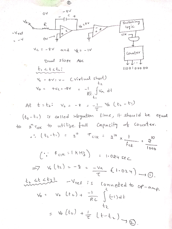
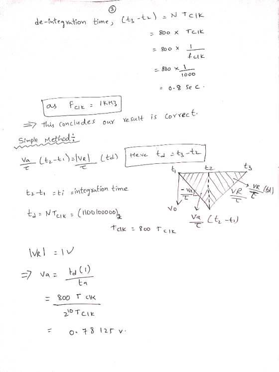
Problem 6 Consider a 10-bit dual slop analog-to-digital converter, with reference voltage of -1V, and a clock frequ...
DILU 2d) Analog and Digital Signals i. A 10-bit linear analog-to-digital has reference voltage 3.3 V...
 DILU 2d) Analog and Digital Signals i. A 10-bit linear analog-to-digital has reference voltage 3.3 V such that it operates correct. for input voltage Vin in the range 0 < Vin < 3.3 V. What is its output, in unsigned binary when Vin = 2.267 V? - ii. What is the quantisation error (in volts) for a 10-bit linear analog-to-digital converter with reference voltage 3.3 V?
Determine the conversion time for an 8-bit SAR Analog to Digital Converter if the clock frequency...
Determine the conversion time for an 8-bit SAR Analog to Digital Converter if the clock frequency is 50kHz:
An 10-bit analog-to-digital converter (ADC) has a voltage range of 0 to 12 V and a digitization uncertainty of ±1 LSB. W...
An 10-bit analog-to-digital converter (ADC) has a voltage range of 0 to 12 V and a digitization uncertainty of ±1 LSB. What is the maximum uncertainty if the digitization is for a 12 V signal? What is the maximum uncertainty for a 18-bit ADC, and for 43-bit? If this ADC has a conversion time of 73 μs, then what is the highest frequency that can be accurately digitized while satisfying the Nyquist criterion? Answer with proper significant figures.
(a) We have an analogue to digital converter (ADC) described as 8 bit, with a 3V reference and 0V offset. What is the resolution, expressed in millivolts? [2] (b) For an input voltage of 0.6V, what i...
 (a) We have an analogue to digital converter (ADC) described as
8 bit, with a 3V reference and 0V offset. What is the resolution,
expressed in millivolts? [2]
(b) For an input voltage of 0.6V, what is the digital output
value of the ADC described in (a)? Express your answer in both
binary and hexadecimal. [3]
(c) An industrial oven has a thermometer that outputs a voltage
from 0 to 1V for a corresponding range of temperatures of 0 to...
(a) We have an analogue to digital converter (ADC) described as
8 bit, with a 3V reference and 0V offset. What is the resolution,
expressed in millivolts? [2]
(b) For an input voltage of 0.6V, what is the digital output
value of the ADC described in (a)? Express your answer in both
binary and hexadecimal. [3]
(c) An industrial oven has a thermometer that outputs a voltage
from 0 to 1V for a corresponding range of temperatures of 0 to...
ssessment,id=215 Converts a physical variable into an electrical signa O converts an analog signal into o...
 ssessment,id=215 Converts a physical variable into an electrical signa O converts an analog signal into o digitol signal O Converts a digitol signol into an anolog signal QUESTION 4 The basic approach to testing D/A converters is to Ο App ya sequence of binary codes coveringthe full rangeofi put vakes to the creati put vhle ooserv ngt eat stonin o O Single-step the device through its full input range while checking the output with a DMM sepe The Check the...
Problem 6 (15 points): The general structure of an N -bit R-2R ladder digital to analog...
 Problem 6 (15 points): The general structure of an N -bit R-2R ladder digital to analog converter (DAC) is shown below, where the voltages at each of the input pins are either 0 or 4 V (for binary "O" and "1", respectively). Assume N- 5. A stream of 5-bit unsigned integers, x[n], are applied to the input of this ladder in binary format (for example, if x13-12, which is B01100 in binary, then a2 and a3 are 4V while ao,...
 DILU 2d) Analog and Digital Signals i. A 10-bit linear analog-to-digital has reference voltage 3.3 V such that it operates correct. for input voltage Vin in the range 0 < Vin < 3.3 V. What is its output, in unsigned binary when Vin = 2.267 V? - ii. What is the quantisation error (in volts) for a 10-bit linear analog-to-digital converter with reference voltage 3.3 V?
 (a) We have an analogue to digital converter (ADC) described as
8 bit, with a 3V reference and 0V offset. What is the resolution,
expressed in millivolts? [2]
(b) For an input voltage of 0.6V, what is the digital output
value of the ADC described in (a)? Express your answer in both
binary and hexadecimal. [3]
(c) An industrial oven has a thermometer that outputs a voltage
from 0 to 1V for a corresponding range of temperatures of 0 to...
(a) We have an analogue to digital converter (ADC) described as
8 bit, with a 3V reference and 0V offset. What is the resolution,
expressed in millivolts? [2]
(b) For an input voltage of 0.6V, what is the digital output
value of the ADC described in (a)? Express your answer in both
binary and hexadecimal. [3]
(c) An industrial oven has a thermometer that outputs a voltage
from 0 to 1V for a corresponding range of temperatures of 0 to...
 ssessment,id=215 Converts a physical variable into an electrical signa O converts an analog signal into o digitol signal O Converts a digitol signol into an anolog signal QUESTION 4 The basic approach to testing D/A converters is to Ο App ya sequence of binary codes coveringthe full rangeofi put vakes to the creati put vhle ooserv ngt eat stonin o O Single-step the device through its full input range while checking the output with a DMM sepe The Check the...
 Problem 6 (15 points): The general structure of an N -bit R-2R ladder digital to analog converter (DAC) is shown below, where the voltages at each of the input pins are either 0 or 4 V (for binary "O" and "1", respectively). Assume N- 5. A stream of 5-bit unsigned integers, x[n], are applied to the input of this ladder in binary format (for example, if x13-12, which is B01100 in binary, then a2 and a3 are 4V while ao,...
Most questions answered within 3 hours.
-
Please explain steps:
An 80 kg swimmer steps off a platform 10 m above the water...
asked 14 minutes ago -
A lottery exists where balls numbered 1 to 17 are placed in an
urn. To win,...
asked 16 minutes ago -
26) Briefly describe, using words or simple diagrams, the
chemiosmotic theory for coupling oxidation to phosphorylation...
asked 2 hours ago -
Suppose that XX is a random variable with mean 16 and standard
deviation 5 . Also...
asked 3 hours ago -
Calculate the number density of argon gas at a temperature of
24C and a pressure of...
asked 6 hours ago -
Alternative
Classification
How to Estimate
Probabilities from Data? ( For continuous Attributes)
And How to generate...
asked 6 hours ago -
An explosion breaks a 20.0-kg object into three parts. The
object is initially moving at a...
asked 7 hours ago -
Calculate the approximate number of residues of Rubisco, which
is involved in carbon fixation in plants,...
asked 8 hours ago -
Other decisions about scientific claims can have a much broader
impact.ENERGYarrow-10x10.png, environment, health, security - all...
asked 9 hours ago -
I need to write a research paper and work cited about this
topic: The United States...
asked 9 hours ago -
Hello! I was wondering if I could have some help?
If the vapor pressure of carvone...
asked 9 hours ago -
An economist wants to estimate the mean per capita income (in
thousands of dollars) for a...
asked 10 hours ago