

Homework Answers


Add Answer to:
Wood Deck Plan: Part Π-Shear & Bending Moment Diagrams Wood Deck Framing Plan-Dimensions & Loading Unifo...
Wood Deck Plan: Part Π-Shear & Bending Moment Diagrams Wood Deck Framing Plan-Dimensions & Loading Uniformly...
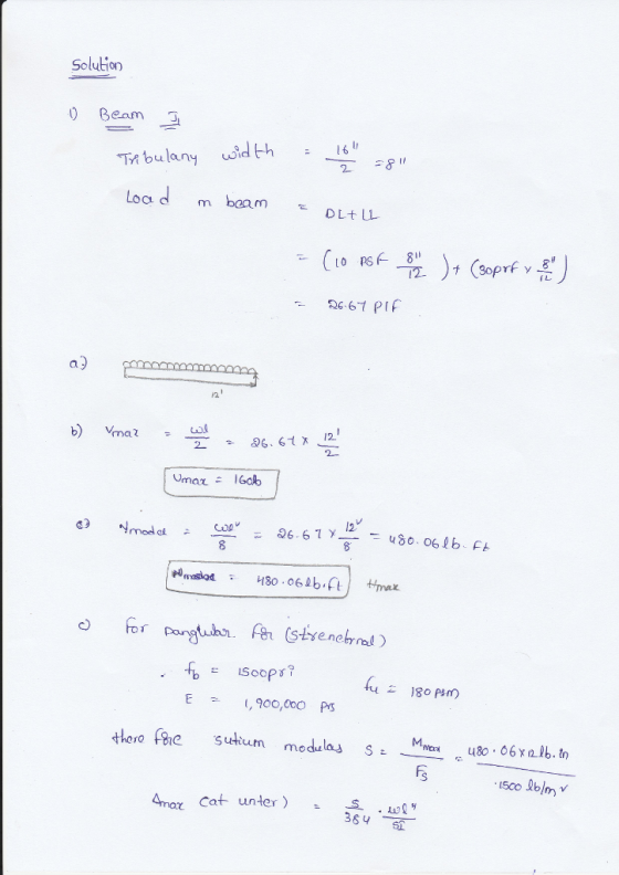
 Wood Deck Plan: Part Π-Shear & Bending Moment Diagrams Wood Deck Framing Plan-Dimensions & Loading Uniformly Distributed Load STUDENTI "A" No. (feet) (feet) (feet) (feet)(inches) Dead Load (#/ft*) Live Load (#/ft2) 30 10 15 15 15 15 18 18 18 18 18 12 14 16 12 14 16 12 14 16 12 16 12 16 12 16 12 16 12 16 12 10 10 10 12 12 12 12 30 5 40 40 50 50 30 30 40 40 5...
QUESTION 4 4. Bending Moment in a Beam Draw the shear and bending moment diagrams for...
 QUESTION 4 4. Bending Moment in a Beam Draw the shear and bending moment diagrams for the beam and loading shown. Then use the bending moment diagram to determine the bending moment in ſkip-ft] experienced by the beam at point D. 12 kips 12 kips 10 kips the С - 5 ft 5ft --- 2 ft 3 ft
For the following diagram, draw the shear and bending-moment diagrams for the beam. The 50 lb/in...
 For the following diagram, draw the shear and bending-moment diagrams for the beam. The 50 lb/in load extends 12 inches from point A. 50 lb/in B С D E 450 lb 12 in. -10 in. 6 in. '4 in. -32 in.-
Shear and Bending Moment Diagrams Learning Goal: To determine the reactive forces and moments acting on...
 Shear and Bending Moment Diagrams
Learning Goal:
To determine the reactive forces and moments acting on a beam;
express the shear and bending moment as functions of their
positions along the beam; and construct shear and bending moment
diagrams.
The cantilever beam shown is subjected to a moment at A
and a distributed load that acts over segment BC, and is
fixed at C. Determine the reactions at the support located
at C. Then write expressions for shear and bending...
Shear and Bending Moment Diagrams
Learning Goal:
To determine the reactive forces and moments acting on a beam;
express the shear and bending moment as functions of their
positions along the beam; and construct shear and bending moment
diagrams.
The cantilever beam shown is subjected to a moment at A
and a distributed load that acts over segment BC, and is
fixed at C. Determine the reactions at the support located
at C. Then write expressions for shear and bending...
Draw the shear force and bending-moment diagrams for the simply supported beam shown. Label each diagram...
 Draw the shear force and bending-moment diagrams for the simply
supported beam shown. Label each diagram with the corresponding
values
1. Draw the shear force and bending-moment diagrams for the simply supported beam shown. Label each diagram with the corresponding values. 3 Pe= 30 KN 4 m - m 3 m - C -40 kN - m
Draw the shear force and bending-moment diagrams for the simply
supported beam shown. Label each diagram with the corresponding
values
1. Draw the shear force and bending-moment diagrams for the simply supported beam shown. Label each diagram with the corresponding values. 3 Pe= 30 KN 4 m - m 3 m - C -40 kN - m
Use the graphical method to construct the shear-force and bending-moment diagrams for the beam shown. Label...
 Use the graphical method to construct the shear-force and bending-moment diagrams for the beam shown. Label all significant points on each diagram and identify the maximum moments along with their respective locations. Additionally: (a) Determine V and M in the beam at a point located 1.50 m to the right of B. (b) Determine Vand M in the beam at a point located 1.25 m to the left of D. Leta - 3.0m, b = 6.1 m,w = 38 kN/m,...
Use the graphical method to construct the shear and bending-moment diagrams for the beam and loading. Label all significant points on each diagram and identify the maximum moments along with their respective locations.
 Problem #1-#5. Use the graphical method to construct the shear and bending-moment diagrams for the beam and loading. Label all significant points on each diagram and identify the maximum moments along with their respective locations. Additionally, for Problem 1-3, you need to do the following Problem #1: Determine the maximum normal stress due to bending Problem #2: Determine V and M in the beam at a point located 0.75 m to the right of B and determine V and M in the beam...
Part 1 Use the graphical method to construct the shear-force and bending moment diagrams for the...
 Part 1 Use the graphical method to construct the shear-force and bending moment diagrams for the beam shown. Let a-3.s ftt, he eshe 10.5 kipe/ft and p 105 kigs. Construct the shear-force and bending-moment diagrams on paper and use the results to subsequent parts of this GO exercise. For this loading, calculate the reaction forces Ay and Ey acting on the beam. Positive values for the reactions are indicated by the directions of the red arrows shown on the free-body...
\Please help me to do part (c)Part c) Using the shear and moment diagrams created for...
 \Please help me to do part (c)Part c) Using the shear and
moment diagrams created for the beam shown in “c” determine the
maximum bending stress created for the largest positive bending
moment and the largest negative bending moment. Consider the beam
to be a W 12 x 79.
Part a) Draw the shear and bending moment diagrams. Clearly show the values, slopes, and degree of curves (e.g., parabola, 3rd degree polynomial). 10 k 20 k 20 k 75 kN...
\Please help me to do part (c)Part c) Using the shear and
moment diagrams created for the beam shown in “c” determine the
maximum bending stress created for the largest positive bending
moment and the largest negative bending moment. Consider the beam
to be a W 12 x 79.
Part a) Draw the shear and bending moment diagrams. Clearly show the values, slopes, and degree of curves (e.g., parabola, 3rd degree polynomial). 10 k 20 k 20 k 75 kN...
1. (8 pts) (a) Generate the shear and bending moment diagrams below for beam subject to...
 1. (8 pts) (a) Generate the shear and bending moment diagrams below for beam subject to the loads shown below. Take pin A on the beam as x-.Attached your graphs to this coversheet and include the detailed equations for both V(C) and M(x) for each segment of the graphs. (b) (2) From your graphs, find the value of x where the magnitude of the bending moment is maximum and report (Mx) at this point X- ーm @IMIMma.- kN m 24...
 Wood Deck Plan: Part Π-Shear & Bending Moment Diagrams Wood Deck Framing Plan-Dimensions & Loading Uniformly Distributed Load STUDENTI "A" No. (feet) (feet) (feet) (feet)(inches) Dead Load (#/ft*) Live Load (#/ft2) 30 10 15 15 15 15 18 18 18 18 18 12 14 16 12 14 16 12 14 16 12 16 12 16 12 16 12 16 12 16 12 10 10 10 12 12 12 12 30 5 40 40 50 50 30 30 40 40 5...
 QUESTION 4 4. Bending Moment in a Beam Draw the shear and bending moment diagrams for the beam and loading shown. Then use the bending moment diagram to determine the bending moment in ſkip-ft] experienced by the beam at point D. 12 kips 12 kips 10 kips the С - 5 ft 5ft --- 2 ft 3 ft
 For the following diagram, draw the shear and bending-moment diagrams for the beam. The 50 lb/in load extends 12 inches from point A. 50 lb/in B С D E 450 lb 12 in. -10 in. 6 in. '4 in. -32 in.-
 Shear and Bending Moment Diagrams
Learning Goal:
To determine the reactive forces and moments acting on a beam;
express the shear and bending moment as functions of their
positions along the beam; and construct shear and bending moment
diagrams.
The cantilever beam shown is subjected to a moment at A
and a distributed load that acts over segment BC, and is
fixed at C. Determine the reactions at the support located
at C. Then write expressions for shear and bending...
Shear and Bending Moment Diagrams
Learning Goal:
To determine the reactive forces and moments acting on a beam;
express the shear and bending moment as functions of their
positions along the beam; and construct shear and bending moment
diagrams.
The cantilever beam shown is subjected to a moment at A
and a distributed load that acts over segment BC, and is
fixed at C. Determine the reactions at the support located
at C. Then write expressions for shear and bending...
 Draw the shear force and bending-moment diagrams for the simply
supported beam shown. Label each diagram with the corresponding
values
1. Draw the shear force and bending-moment diagrams for the simply supported beam shown. Label each diagram with the corresponding values. 3 Pe= 30 KN 4 m - m 3 m - C -40 kN - m
Draw the shear force and bending-moment diagrams for the simply
supported beam shown. Label each diagram with the corresponding
values
1. Draw the shear force and bending-moment diagrams for the simply supported beam shown. Label each diagram with the corresponding values. 3 Pe= 30 KN 4 m - m 3 m - C -40 kN - m
 Use the graphical method to construct the shear-force and bending-moment diagrams for the beam shown. Label all significant points on each diagram and identify the maximum moments along with their respective locations. Additionally: (a) Determine V and M in the beam at a point located 1.50 m to the right of B. (b) Determine Vand M in the beam at a point located 1.25 m to the left of D. Leta - 3.0m, b = 6.1 m,w = 38 kN/m,...
 Part 1 Use the graphical method to construct the shear-force and bending moment diagrams for the beam shown. Let a-3.s ftt, he eshe 10.5 kipe/ft and p 105 kigs. Construct the shear-force and bending-moment diagrams on paper and use the results to subsequent parts of this GO exercise. For this loading, calculate the reaction forces Ay and Ey acting on the beam. Positive values for the reactions are indicated by the directions of the red arrows shown on the free-body...
 \Please help me to do part (c)Part c) Using the shear and
moment diagrams created for the beam shown in “c” determine the
maximum bending stress created for the largest positive bending
moment and the largest negative bending moment. Consider the beam
to be a W 12 x 79.
Part a) Draw the shear and bending moment diagrams. Clearly show the values, slopes, and degree of curves (e.g., parabola, 3rd degree polynomial). 10 k 20 k 20 k 75 kN...
\Please help me to do part (c)Part c) Using the shear and
moment diagrams created for the beam shown in “c” determine the
maximum bending stress created for the largest positive bending
moment and the largest negative bending moment. Consider the beam
to be a W 12 x 79.
Part a) Draw the shear and bending moment diagrams. Clearly show the values, slopes, and degree of curves (e.g., parabola, 3rd degree polynomial). 10 k 20 k 20 k 75 kN...
 1. (8 pts) (a) Generate the shear and bending moment diagrams below for beam subject to the loads shown below. Take pin A on the beam as x-.Attached your graphs to this coversheet and include the detailed equations for both V(C) and M(x) for each segment of the graphs. (b) (2) From your graphs, find the value of x where the magnitude of the bending moment is maximum and report (Mx) at this point X- ーm @IMIMma.- kN m 24...
Most questions answered within 3 hours.
-
X Company is trying to decide whether to continue using old
equipment to make Product A...
asked 24 minutes ago -
Minitab Problem: Take the Lake Hume June rainfall data and find
use the processes outlined in...
asked 23 minutes ago -
IN PYTHON ONLY !! Program 2: Re-work
program #5 (WeeklyHours) from the previous assignment such that...
asked 1 hour ago -
The average length of time between arrivals at a turnpike
toll-booth is 26 seconds. What is...
asked 2 hours ago -
(a) A piston at 6.1 atm contains a gas that occupies a volume of
3.5 L....
asked 3 hours ago -
Please answer true or false. Words
cannot be changed or added in to make it true...
asked 3 hours ago -
An empty test tube weighs 15.923 grams. Then,
MgCl2•6H2O is added into the test tube. After...
asked 3 hours ago -
Assume memory access is 10 units of time and disk access is
10000 units of time....
asked 4 hours ago -
1. Are all good samples random?
2. Magazines often report surveys giving statistics such as “63%...
asked 4 hours ago -
Under all the various types of market structures, firms
must eventually earn some economic profits for...
asked 4 hours ago -
Consider the following fitness regime for a single locus trait
with two co-dominant alleles: w11 =...
asked 4 hours ago -
A large cable company reports the following.
80% of its customers subscribe to its cable TV...
asked 4 hours ago