For these two E-R diagrams below transform the diagram to a relational schema that shows referential integrity constrai...
For these two E-R diagrams below transform the diagram to a
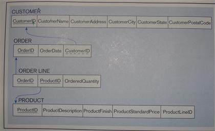
relational schema that shows referential integrity constraints (see
Figure 4-5 for an example of such a schema).
Figure 4-5:
A.

B.

Homework Answers
Looking at the first problem, I imagine that you will need a table to represent the relationship attribute of completion date. Given the examples, here's what I've come up with for number A:

Here's the MySQL table creation code:
create table `EMPLOYEE`
(
        `Employee ID` int(10) unsigned not null auto_increment,
        `Employee Name` varchar(128) not null,
        #Other optional data goes here.
        `Birth Date` datetime not null,
        primary key (`Employee ID`),
        unique key `Employee ID` (`Employee ID`)
) engine=InnoDB default charset=utf8;

create table `COURSE`
(
        `Course ID` int(10) unsigned not null auto_increment,
        `Course Title` varchar(128) not null,
        `Topic` text default null,
        primary key (`Course ID`),
        unique key `Course ID` (`Course ID`)
) engine=InnoDB default charset=utf8;

create table `COMPLETION` # This is your relationship attribute
(
        `Course ID` int(10) unsigned not null,
        `Employee ID` int(10) unsigned not null,
        `Date Completed` datetime not null,
        primary key (`Course ID`, `Employee ID`),
        unique key `Course ID and Employee ID` (`Course ID`, `Employee ID`),
        constraint `Course ID Foreign Key`
                foreign key (`Course ID`)
                references `COURSE` (`Course ID`),
        constraint `Employee ID Foreign Key`
                foreign key (`Employee ID`)
                references `EMPLOYEE` (`Employee ID`)
) engine=InnoDB default charset=utf8;
Note that even though we have two one-to-many relationships, this has the net effect of creating a many-to-many relationship between the COURSE and EMPLOYEE tables. Note also that the relationships formed by the foreign keys in COMPLETION are identifying relationships.
Next, for problem B, you will see that the situation is quite similar:

And again, here's the MySQL code:
create table `EMPLOYEE`
(
        `Employee ID` int(10) unsigned not null auto_increment,
        `Employee Name` varchar(128) not null,
        #Other optional data goes here.
        `Birth Date` datetime not null,
        primary key (`Employee ID`),
        unique key `Employee ID` (`Employee ID`)
) engine=InnoDB default charset=utf8;

create table `COURSE`
(
        `Course ID` int(10) unsigned not null auto_increment,
        `Course Title` varchar(128) not null,
        `Topic` text default null,
        primary key (`Course ID`),
        unique key `Course ID` (`Course ID`)
) engine=InnoDB default charset=utf8;

create table `CERTIFICATE`
(
        `Certificate Number` int(10) unsigned not null auto_increment,
        `Course ID` int(10) unsigned not null,
        `Employee ID` int(10) unsigned not null,
        `Date Completed` datetime not null,
        primary key (`Certificate Number`),
        unique key `Certificate Number` (`Certificate Number`),
        constraint `Course ID Foreign Key`
                foreign key (`Course ID`)
                references `COURSE` (`Course ID`),
        constraint `Employee ID Foreign Key`
                foreign key (`Employee ID`)
                references `EMPLOYEE` (`Employee ID`)
) engine=InnoDB default charset=utf8;
Note that, unlike the relationships formed by the foreign keys in answer A, the relationships formed by the foreign keys in CERTIFICATE are non-identifying relationships.
Please also note that the answer I am providing for you is an example of how I would implement the exercises in question. Your instructor may be looking for something fundamentally different. Also, I am making an educated guess as to what the various and sundry underlinings, boldfacings, and parenthetical bits mean. Hopefully, this will be of help to you. I encourage that you spend some time studying the concepts of data normalization.
Add Answer to:
For these two E-R diagrams below transform the diagram to a relational schema that shows referential integrity constrai...
Help! Relational schema that shows referential integrity constraints
 1.For each of the following E-R diagrams from Chapter 2:I. Transform the diagram to a relational schema that shows referential integrity constraints (see Figure 4-5 for an example of such a schema).Figure 4-5:Figure 2-8Figure 2-9bFigure 2-11aFigure 2-11bFigure 2-15a (relationship version)Figure 2-15b (attribute version)Figure 2-16bFigure 2-19*These E-R diagrams are shown below:a. Figure 2-8:b. Figure 2-9b:c. Figure 2-11a:d. Figure 2-11b:e. Figure 2-15a (relationship version):f. Figure 2-15b (attribute version):g. Figure 2-16b:h. Figure 2-19:
I need a solution for this please Transform the following diagram to a relational schema that shows referential...
 I need a solution for this please
Transform the following diagram to a relational schema that shows referential integrity constraints.
I need a solution for this please
Transform the following diagram to a relational schema that shows referential integrity constraints.
Database: Convert E-R diagrams to relational schema and show • Primary Keys (using underline) • Foreign Keys (using dotted underline) • Referential Integrity Convert the E-R diagrams to relational s...
 Database: Convert E-R diagrams to relational schema and show
• Primary Keys (using underline)
• Foreign Keys (using dotted underline)
• Referential Integrity
Convert the E-R diagrams to relational schema and show: Primary Keys (using underline) Foreign Keys (using dotted underline) . Referential Integrity Your schema should look similar to the example below. CUSTOMER CustName ORDER PROJECT Foect Title EMPLOYEE PROJECT assigecl to Tite BBli EMPLOYEE PROJECT 0 ProectTitle 4 student admitdate D,C gradstudent advisor major mimor class person name...
Database: Convert E-R diagrams to relational schema and show
• Primary Keys (using underline)
• Foreign Keys (using dotted underline)
• Referential Integrity
Convert the E-R diagrams to relational schema and show: Primary Keys (using underline) Foreign Keys (using dotted underline) . Referential Integrity Your schema should look similar to the example below. CUSTOMER CustName ORDER PROJECT Foect Title EMPLOYEE PROJECT assigecl to Tite BBli EMPLOYEE PROJECT 0 ProectTitle 4 student admitdate D,C gradstudent advisor major mimor class person name...
Need assistance with this question. Please show detailed steps. For each of the following (parts a through g) E-R di...
 Need assistance with this question. Please show detailed steps.
For each of the following (parts a through g) E-R diagrams: L. Transform the diagram to a relational schema that shows referential integrity constraints (see the following figure for an example of such a schema - underlined items are primary keys, dotted underlines refer to foreign keys, while the arrows indicate direction from foreign to primary) CUSTOMER CustomerlD CustomerName ORDER OrderlD OrderDate CustomerlD ORDER LINE OrderlD rd OrderedQuantity PRODUCT roductD ProductDescription
Need assistance with this question. Please show detailed steps.
For each of the following (parts a through g) E-R diagrams: L. Transform the diagram to a relational schema that shows referential integrity constraints (see the following figure for an example of such a schema - underlined items are primary keys, dotted underlines refer to foreign keys, while the arrows indicate direction from foreign to primary) CUSTOMER CustomerlD CustomerName ORDER OrderlD OrderDate CustomerlD ORDER LINE OrderlD rd OrderedQuantity PRODUCT roductD ProductDescription
Map the ER diagram into a relational database schema. Describe each relation schema in parenthesized notation...
Map the ER diagram into a relational database schema. Describe each relation schema in parenthesized notation (not SQL) underlining the primary key. For each relation, describe any applicable integrity constraints, e.g., foreign key, referential integrity, not null, etc.
a) Identify the foreign keys in this schema. Explain how the entity and referential integrity rules...
a) Identify the foreign keys in this schema. Explain how the entity and referential integrity rules apply to these relations. b) Produce some sample tables for these relations that observe the relational in- tegrity rules. Suggest some general constraints that would be appropriate for this schema.
Question 5: ERD and Relational Schema 10 marks Figure 1 shows an ER diagram for a...
 Question 5: ERD and Relational Schema 10 marks Figure 1 shows an ER diagram for a university dining services organization that provides dining services to a university. 1- Transform the diagram to a set of relations and develop a relational schema (5 marks) Find the functional dependencies in the relations and determine their normal forms (5 2- marks) MENU EVENT Served at Event ID Menu ID Event Location Menu Description Event Time Menu Type Contains Supervises DISH WORK SCHEDULE STAFF...
Question II TRANSFORM THE E-R Diagram into the Relational Model Please convert the E-R diagram below...
 Question II TRANSFORM THE E-R Diagram into the Relational Model Please convert the E-R diagram below to a relational model. · E-R diagram for customers and loans: name street_address ( loan id (access_date) amount cust_id - city ) customer borrower loan
3.1 (12) Transform the following ER diagram into a relational schema diagram. Semester Year Cno Title...
 3.1 (12) Transform the following ER diagram into a relational schema diagram. Semester Year Cno Title SecNo Term --- ssn Name Course E belongs 0cl Section so Teaches Teacher
 I need a solution for this please
Transform the following diagram to a relational schema that shows referential integrity constraints.
I need a solution for this please
Transform the following diagram to a relational schema that shows referential integrity constraints.
 Database: Convert E-R diagrams to relational schema and show
• Primary Keys (using underline)
• Foreign Keys (using dotted underline)
• Referential Integrity
Convert the E-R diagrams to relational schema and show: Primary Keys (using underline) Foreign Keys (using dotted underline) . Referential Integrity Your schema should look similar to the example below. CUSTOMER CustName ORDER PROJECT Foect Title EMPLOYEE PROJECT assigecl to Tite BBli EMPLOYEE PROJECT 0 ProectTitle 4 student admitdate D,C gradstudent advisor major mimor class person name...
Database: Convert E-R diagrams to relational schema and show
• Primary Keys (using underline)
• Foreign Keys (using dotted underline)
• Referential Integrity
Convert the E-R diagrams to relational schema and show: Primary Keys (using underline) Foreign Keys (using dotted underline) . Referential Integrity Your schema should look similar to the example below. CUSTOMER CustName ORDER PROJECT Foect Title EMPLOYEE PROJECT assigecl to Tite BBli EMPLOYEE PROJECT 0 ProectTitle 4 student admitdate D,C gradstudent advisor major mimor class person name...
 Need assistance with this question. Please show detailed steps.
For each of the following (parts a through g) E-R diagrams: L. Transform the diagram to a relational schema that shows referential integrity constraints (see the following figure for an example of such a schema - underlined items are primary keys, dotted underlines refer to foreign keys, while the arrows indicate direction from foreign to primary) CUSTOMER CustomerlD CustomerName ORDER OrderlD OrderDate CustomerlD ORDER LINE OrderlD rd OrderedQuantity PRODUCT roductD ProductDescription
Need assistance with this question. Please show detailed steps.
For each of the following (parts a through g) E-R diagrams: L. Transform the diagram to a relational schema that shows referential integrity constraints (see the following figure for an example of such a schema - underlined items are primary keys, dotted underlines refer to foreign keys, while the arrows indicate direction from foreign to primary) CUSTOMER CustomerlD CustomerName ORDER OrderlD OrderDate CustomerlD ORDER LINE OrderlD rd OrderedQuantity PRODUCT roductD ProductDescription
 Question 5: ERD and Relational Schema 10 marks Figure 1 shows an ER diagram for a university dining services organization that provides dining services to a university. 1- Transform the diagram to a set of relations and develop a relational schema (5 marks) Find the functional dependencies in the relations and determine their normal forms (5 2- marks) MENU EVENT Served at Event ID Menu ID Event Location Menu Description Event Time Menu Type Contains Supervises DISH WORK SCHEDULE STAFF...
 Question II TRANSFORM THE E-R Diagram into the Relational Model Please convert the E-R diagram below to a relational model. · E-R diagram for customers and loans: name street_address ( loan id (access_date) amount cust_id - city ) customer borrower loan
 3.1 (12) Transform the following ER diagram into a relational schema diagram. Semester Year Cno Title SecNo Term --- ssn Name Course E belongs 0cl Section so Teaches Teacher
Most questions answered within 3 hours.
-
Write a program to solve the Josephus problem, with the following
modification:
Sample Input:
./a.out n...
asked 1 hour ago -
At the start of a CD it is spinning at a rate of 525 rpm
(revolutions...
asked 2 hours ago -
4. Without doing any calculations, predict whether the observed
∆T would increase, decrease or remain the...
asked 3 hours ago -
Based on the range, which of the following sets of scores has
the greatest variability? 3,...
asked 4 hours ago -
Ripples in a pond travel at a velocity of 3 m/s with one peak
passing a...
asked 4 hours ago -
A man stands on the roof of a building of height 13.0 mm and
throws a...
asked 4 hours ago -
The extent to which assets are financed by borrowed funds and
other liabilities is indicated by:...
asked 5 hours ago -
Explain in detail
Germany is the fifth largest economy
explain what goods and services Germany specializes...
asked 5 hours ago -
The density of platinum is 21.45 g/mL. If a cube of platinum
with a mass of...
asked 5 hours ago -
Accounts Receivable
Sales
A/R Posting
Extended Sales Invoice
Packing Slip
Compare invoice to packing slip 2...
asked 5 hours ago -
Michaella, age 23, is a full-time law student and is claimed by
her parents as a...
asked 5 hours ago -
Why are polymers not typically casted into products?
asked 6 hours ago