
need answers to the three questions
Homework Answers


Add Answer to:
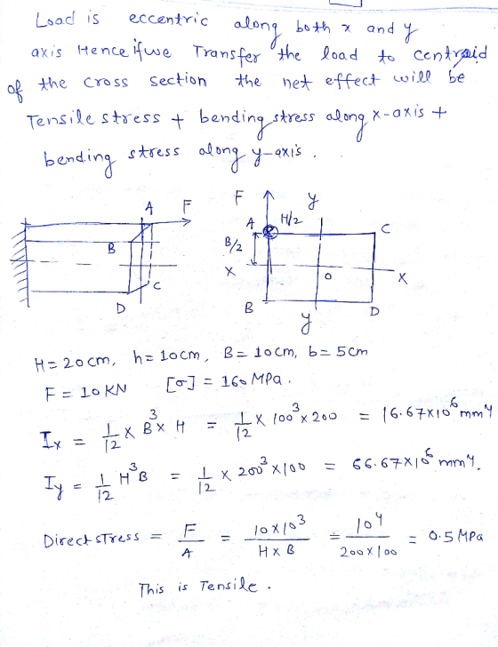
need answers to the three questions 10kN,(o|-160 MPa . 20 cm. h = 10cm, B =10cm, b = 5 cm, F Given: H l: 1) calculat...
need solution of the two quedtions Given: q -10kN/m, P- 20kN, M-10kNm:-160 MPa; a 2m, Goal: l) write the equations o...
 need solution of the two quedtions
Given: q -10kN/m, P- 20kN, M-10kNm:-160 MPa; a 2m, Goal: l) write the equations of intern tions of the rod system and draw the graphs of their distributions along the length of rod portions; 2) for the last portion: a) calculate the diameter of round solid cross-section; b) dimensions of rectangle solid cross-section in hib 2. al forces and moments in an arbitrary cross-
Given: q -10kN/m, P- 20kN, M-10kNm:-160 MPa; a 2m, Goal:...
need solution of the two quedtions
Given: q -10kN/m, P- 20kN, M-10kNm:-160 MPa; a 2m, Goal: l) write the equations of intern tions of the rod system and draw the graphs of their distributions along the length of rod portions; 2) for the last portion: a) calculate the diameter of round solid cross-section; b) dimensions of rectangle solid cross-section in hib 2. al forces and moments in an arbitrary cross-
Given: q -10kN/m, P- 20kN, M-10kNm:-160 MPa; a 2m, Goal:...
The point loads are placed at the fixed positions shown in the figure and they are...
 The point loads are placed at the fixed positions shown in the figure and they are live loads. E C (centre) f = 32 Mpa fer= 3 MPa fsv = 500 MPa E = 200 GPa E = 28600 MPa a Cross section The following values are used for the question. . l = 3 m load before cracking • 12 = 2.5 m . P = 2 KN . a = 50 mm . G-5 kN/m • b =...
The beam shown (Figure 1) is supported by a pin at A and a cable at...
 The beam shown (Figure 1) is supported by a pin at A
and a cable at B. Two loads P = 13 kN are applied
straight down from the centerline of the bottom face. Determine the
state of stress at the point shown (Figure 2) in a section 2 m from
the wall. The dimensions are w = 5.2 cm , h =
10.5 cm , L = 0.8 m , a = 1.5 cm , and b
= 4...
The beam shown (Figure 1) is supported by a pin at A
and a cable at B. Two loads P = 13 kN are applied
straight down from the centerline of the bottom face. Determine the
state of stress at the point shown (Figure 2) in a section 2 m from
the wall. The dimensions are w = 5.2 cm , h =
10.5 cm , L = 0.8 m , a = 1.5 cm , and b
= 4...
The beam shown (Figure 1) is supported by a pin at A and a cable at...
 The beam shown (Figure 1) is supported by a pin at A and a cable at
B. Two loads P = 13 kN are applied straight down
from the centerline of the bottom face. Determine the state of
stress at the point shown (Figure 2) in a section 2 m from the
wall. The dimensions are w = 5.2 cm , h = 10.5 cm
, L = 0.8 m , a = 1.5 cm , and b = 4...
The beam shown (Figure 1) is supported by a pin at A and a cable at
B. Two loads P = 13 kN are applied straight down
from the centerline of the bottom face. Determine the state of
stress at the point shown (Figure 2) in a section 2 m from the
wall. The dimensions are w = 5.2 cm , h = 10.5 cm
, L = 0.8 m , a = 1.5 cm , and b = 4...
The beam shown (Figure 1) is supported by a pin at A and a cable at...
 The beam shown (Figure 1) is
supported by a pin at A and a cable at B. Two
loads P = 13 kN are applied straight down from the
centerline of the bottom face. Determine the state of stress at the
point shown (Figure 2) in a section 2 m from the wall. The
dimensions are w = 5.2 cm , h = 10.5 cm ,
L = 0.8 m , a = 1.5 cm , and b = 4...
The beam shown (Figure 1) is
supported by a pin at A and a cable at B. Two
loads P = 13 kN are applied straight down from the
centerline of the bottom face. Determine the state of stress at the
point shown (Figure 2) in a section 2 m from the wall. The
dimensions are w = 5.2 cm , h = 10.5 cm ,
L = 0.8 m , a = 1.5 cm , and b = 4...
Part B?? An l-beam has a flange width b-250 mm , height h = 250 mm...
 Part B??
An l-beam has a flange width b-250 mm , height h = 250 mm , web thickness tw-9 mm , and flange thickness tf = 14 mm . Use the following steps to calculate the shear flow at the point shown, where z = 80 mm Learning Goal: To calculate the shear flow at a point in the flange of an I-beam section subject to a shear force. A thin-walled structure is one where the wall thickness is...
Part B??
An l-beam has a flange width b-250 mm , height h = 250 mm , web thickness tw-9 mm , and flange thickness tf = 14 mm . Use the following steps to calculate the shear flow at the point shown, where z = 80 mm Learning Goal: To calculate the shear flow at a point in the flange of an I-beam section subject to a shear force. A thin-walled structure is one where the wall thickness is...
A B C D E F G H 1 J K L M N 0 P...
 A B C D E F G H 1 J K L M N 0 P Q Exercise Single shear test of timber Insert any discussions/comments on this page For the data provided in the table below, determine the single shear strength for each test regime. Also, comment on the respective test results, whether they are satisfactory or not. Note: The cells for 'Area of cross section', and 'Single shear stress' are not locked for editing Failure load, N Single...
A 3 m rigid bar AB is supported with a vertical translational spring at A and a pin at B The bar is subjected to a linearly varying distributed load with maximum intensity g Calculate the ver...
 A 3 m rigid bar AB is supported with a vertical translational spring at A and a pin at B The bar is subjected to a linearly varying distributed load with maximum intensity g Calculate the vertical deformation of the spring if the spring constant is 700 kN/m. (ans: 21.43 mm) 2. A steel cable with a nominal diameter of 25 mm is used in a construction yard to lift a bridge section weighing 38 kN. The cable has an...
 need solution of the two quedtions
Given: q -10kN/m, P- 20kN, M-10kNm:-160 MPa; a 2m, Goal: l) write the equations of intern tions of the rod system and draw the graphs of their distributions along the length of rod portions; 2) for the last portion: a) calculate the diameter of round solid cross-section; b) dimensions of rectangle solid cross-section in hib 2. al forces and moments in an arbitrary cross-
Given: q -10kN/m, P- 20kN, M-10kNm:-160 MPa; a 2m, Goal:...
need solution of the two quedtions
Given: q -10kN/m, P- 20kN, M-10kNm:-160 MPa; a 2m, Goal: l) write the equations of intern tions of the rod system and draw the graphs of their distributions along the length of rod portions; 2) for the last portion: a) calculate the diameter of round solid cross-section; b) dimensions of rectangle solid cross-section in hib 2. al forces and moments in an arbitrary cross-
Given: q -10kN/m, P- 20kN, M-10kNm:-160 MPa; a 2m, Goal:...
 The point loads are placed at the fixed positions shown in the figure and they are live loads. E C (centre) f = 32 Mpa fer= 3 MPa fsv = 500 MPa E = 200 GPa E = 28600 MPa a Cross section The following values are used for the question. . l = 3 m load before cracking • 12 = 2.5 m . P = 2 KN . a = 50 mm . G-5 kN/m • b =...
 The beam shown (Figure 1) is supported by a pin at A
and a cable at B. Two loads P = 13 kN are applied
straight down from the centerline of the bottom face. Determine the
state of stress at the point shown (Figure 2) in a section 2 m from
the wall. The dimensions are w = 5.2 cm , h =
10.5 cm , L = 0.8 m , a = 1.5 cm , and b
= 4...
The beam shown (Figure 1) is supported by a pin at A
and a cable at B. Two loads P = 13 kN are applied
straight down from the centerline of the bottom face. Determine the
state of stress at the point shown (Figure 2) in a section 2 m from
the wall. The dimensions are w = 5.2 cm , h =
10.5 cm , L = 0.8 m , a = 1.5 cm , and b
= 4...
 The beam shown (Figure 1) is supported by a pin at A and a cable at
B. Two loads P = 13 kN are applied straight down
from the centerline of the bottom face. Determine the state of
stress at the point shown (Figure 2) in a section 2 m from the
wall. The dimensions are w = 5.2 cm , h = 10.5 cm
, L = 0.8 m , a = 1.5 cm , and b = 4...
The beam shown (Figure 1) is supported by a pin at A and a cable at
B. Two loads P = 13 kN are applied straight down
from the centerline of the bottom face. Determine the state of
stress at the point shown (Figure 2) in a section 2 m from the
wall. The dimensions are w = 5.2 cm , h = 10.5 cm
, L = 0.8 m , a = 1.5 cm , and b = 4...
 The beam shown (Figure 1) is
supported by a pin at A and a cable at B. Two
loads P = 13 kN are applied straight down from the
centerline of the bottom face. Determine the state of stress at the
point shown (Figure 2) in a section 2 m from the wall. The
dimensions are w = 5.2 cm , h = 10.5 cm ,
L = 0.8 m , a = 1.5 cm , and b = 4...
The beam shown (Figure 1) is
supported by a pin at A and a cable at B. Two
loads P = 13 kN are applied straight down from the
centerline of the bottom face. Determine the state of stress at the
point shown (Figure 2) in a section 2 m from the wall. The
dimensions are w = 5.2 cm , h = 10.5 cm ,
L = 0.8 m , a = 1.5 cm , and b = 4...
 Part B??
An l-beam has a flange width b-250 mm , height h = 250 mm , web thickness tw-9 mm , and flange thickness tf = 14 mm . Use the following steps to calculate the shear flow at the point shown, where z = 80 mm Learning Goal: To calculate the shear flow at a point in the flange of an I-beam section subject to a shear force. A thin-walled structure is one where the wall thickness is...
Part B??
An l-beam has a flange width b-250 mm , height h = 250 mm , web thickness tw-9 mm , and flange thickness tf = 14 mm . Use the following steps to calculate the shear flow at the point shown, where z = 80 mm Learning Goal: To calculate the shear flow at a point in the flange of an I-beam section subject to a shear force. A thin-walled structure is one where the wall thickness is...
 A B C D E F G H 1 J K L M N 0 P Q Exercise Single shear test of timber Insert any discussions/comments on this page For the data provided in the table below, determine the single shear strength for each test regime. Also, comment on the respective test results, whether they are satisfactory or not. Note: The cells for 'Area of cross section', and 'Single shear stress' are not locked for editing Failure load, N Single...
 A 3 m rigid bar AB is supported with a vertical translational spring at A and a pin at B The bar is subjected to a linearly varying distributed load with maximum intensity g Calculate the vertical deformation of the spring if the spring constant is 700 kN/m. (ans: 21.43 mm) 2. A steel cable with a nominal diameter of 25 mm is used in a construction yard to lift a bridge section weighing 38 kN. The cable has an...
Most questions answered within 3 hours.
-
The Gross Profit ratio for 2014 is 57.07%
Assume that Campbell's net sales for the first...
asked 2 minutes ago -
You have conducted an experiment to try to demonstrate that
growth factor receptor X protein (GFRX)...
asked 2 minutes ago -
Thoroughly discuss the various current and proposed solutions to
anthropogenic influences resulting in Global Climate Change....
asked 6 minutes ago -
BLOG EXERCISE: You are writing a weekly intranet blog for the
CEO of a large Canadian...
asked 9 minutes ago -
calculate ΔGrxn at 36 ∘C. N2O4(g)→2NO2(g)
asked 9 minutes ago -
Present and Future Values of Single Cash Flows for Different
Periods
Find the following values, using...
asked 12 minutes ago -
Which types of mutations in DNA can lead to the translation of a
non-functional protein product?...
asked 11 minutes ago -
Many structures are composed of individual elements that react
in unison when forces are applied. the...
asked 12 minutes ago -
Work of 1950 J is done by stirring a perfectly insulated beaker
containing 75 g of...
asked 42 minutes ago -
The neighborhood kids set up an outdoor lemonade stand in
Maryland in June. They find that...
asked 44 minutes ago -
9. A company has a beginning inventory of 4,000 units. The
company estimates it will sell...
asked 57 minutes ago -
A patient goes to the doctor's office with symptoms of a urinary
tract infection and provides...
asked 59 minutes ago