The pin - connected rigid rods AB and BC are inclined at theta = 30 when they are unloaded. When the force P is applied theta becomes 30.2. Determine the average normal strain developed in wire AC.

Homework Answers
Normal strain is a measure of longitudinal deformation that is elongation or contraction in the body. Normal strain is denoted by .
Normal stress can be calculated using known values of Young’s modulus and normal strain.
Normal stress is used in various real time applications.
Force is a vector quantity. It is represented by a magnitude, direction, and point of application.
The direction of force can be either compressive or tensile.
The normal strain is calculated as follows:
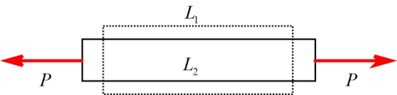
From the figure, initial length is and the final length is .
The normal strain is,
Write the relation to calculate initial length of wire AC.
Here, the length of the rod is L and the angle between the rods before load is applied is .
Substitute for L and for .
Write the relation to calculate final length of wire AC.
Here, the angle between the rods after load is applied is .
Substitute for L and for .
Write the relation to calculate the average normal strain developed in the wire AC.
Substitute for and for .
Ans:
The average normal strain developed in the wire AC is .
Add Answer to:
The pin - connected rigid rods AB and BC are inclined at theta = 30 when they are unloaded. When the force P is applied...
Problem 2.7 7 of 8 The pin-connected rigid rods AB and BC are inclined at θ-30°...
 Problem 2.7 7 of 8 The pin-connected rigid rods AB and BC are inclined at θ-30° when they are unloaded. When the force P is applied θ becomes 30.2°. (Figure 1) Part A Determine the average normal strain developed in wire AC Express your answer using three significant figures vec Figure 1 of 1 Submit Answer Provide Feedback Next> 600 mm
Two rigid rods as shown, AB and BC are connected to a pivot (A) and initially...
 Two rigid rods as shown, AB and BC are connected to a pivot (A)
and initially at rest as shown. Each rod has mass of 3 kg and
length L = 0.5 m. A force P as shown is then applied to rod BC at
some distance b from B (the pivot between bars A and B). Please
find the distance b where, when force P is applied, the two rods
(AB and BC) move together as if they formed...
Two rigid rods as shown, AB and BC are connected to a pivot (A)
and initially at rest as shown. Each rod has mass of 3 kg and
length L = 0.5 m. A force P as shown is then applied to rod BC at
some distance b from B (the pivot between bars A and B). Please
find the distance b where, when force P is applied, the two rods
(AB and BC) move together as if they formed...
Two bars are used to support load P. When unloaded, AB is 5 in. long, AC...
 Two bars are used to support load P. When unloaded, AB is 5 in.
long, AC is 8 in. long, and the ring at A has the coordinates
(0,0). If a load is applied to the ring at A so that it moves to
the coordinate position (0.25 in., -0.73 in.), determine the normal
strain in each bar.
60° 5 in. 8 in.
Two bars are used to support load P. When unloaded, AB is 5 in.
long, AC is 8 in. long, and the ring at A has the coordinates
(0,0). If a load is applied to the ring at A so that it moves to
the coordinate position (0.25 in., -0.73 in.), determine the normal
strain in each bar.
60° 5 in. 8 in.
4) Two rigid rods AC and BC are connected by linear and torsional springs as shown,...
 4) Two rigid rods AC and BC are connected by linear and torsional springs as shown, Determine the critical load Per for buckling of the structure. (12 pts) P. OA 1 kN/m 1.5 m 3 m WWW 3 kN.m 3 m OB
Q.1. (10 Marks) The rigid bar AB is supported by the pin-connected rod BC that has...
 Q.1. (10 Marks) The rigid bar AB is supported by the pin-connected rod BC that has a diameter of 25 mm and is made of A-36 steel (E = 200 GPa). Determine the magnitude of w (kN/m) that is required to displace point B 3 mm downward, 3
A temporary support steel frame (E 200 GPa) is made of 30-mm diameter solid circular steel rods (members AB and CD), an...
 A temporary support steel frame (E 200 GPa) is made of 30-mm diameter solid circular steel rods (members AB and CD), and 22-mm diameter solid circular steel rods (members BC and AD), al pin connected at the turnbuckle corners A, B, C, and D (see Figure below). The steel frame is braced by two cables AC and BD. A turnbuckle is fitted to cable AC and tightening it will induce tension 3m in cable AC. Determine the largest allowable tension...
If the applied force P causes the point B on the rigid arm ABC to be displaced 0.25 mm downward
 If the applied force P causes the point B on the rigid arm ABC to be displaced 0.25 mm downward, determine the normal strain developed in wires BD and CE.
6. Figure 5(a) shows a rigid cylindrical pin of diameter d = 30 mm that is...
 6. Figure 5(a) shows a rigid cylindrical pin of diameter d = 30 mm that is connected to a rigid support through an annular rubber bushing of radial thickness t = 5 mm. A horizontal force F is applied to the pin causing it move horizontally through a distance A = 0.2 mm. Figure 5(b) shows the original and deformed configurations of the small ap- proximately rectangular element identified as A in Figure 5(a) by the angle 0. In particular,...
The rigid bar AB is pinned at A and supported by two aluminum rods (E =...
 The rigid bar AB is pinned at A and supported by two aluminum rods (E = 10 x 103ksi) with diameter d = 1.2 in and the length shown for each on the figure. If the rigid bar is initially vertical, determine (a) the reaction exerted at A and (b) the average normal stress in each rod when the 40-kip force is applied. 40 kip B 2 ft d=12 in ELIF 2 ft- (a) reaction at A 3 ft d=1.2...
The assembly shown in the figure below consists of solid AB, BC and CD rods connected...
 The assembly shown in the figure below consists of solid AB, BC and CD rods connected together, the solid rod AB has 10 mm diameter and 100 mm length, the solid rod BC has 20 mm diameter a 120 mm length, while the solid rod CD has 10 mm diameter and 100 mm length. Allh rods are made of steel with E-200 GPa. the assembly is subjected to 100 kN tensile force (CLO5) The average normal stress between A and...
 Problem 2.7 7 of 8 The pin-connected rigid rods AB and BC are inclined at θ-30° when they are unloaded. When the force P is applied θ becomes 30.2°. (Figure 1) Part A Determine the average normal strain developed in wire AC Express your answer using three significant figures vec Figure 1 of 1 Submit Answer Provide Feedback Next> 600 mm
 Two rigid rods as shown, AB and BC are connected to a pivot (A)
and initially at rest as shown. Each rod has mass of 3 kg and
length L = 0.5 m. A force P as shown is then applied to rod BC at
some distance b from B (the pivot between bars A and B). Please
find the distance b where, when force P is applied, the two rods
(AB and BC) move together as if they formed...
Two rigid rods as shown, AB and BC are connected to a pivot (A)
and initially at rest as shown. Each rod has mass of 3 kg and
length L = 0.5 m. A force P as shown is then applied to rod BC at
some distance b from B (the pivot between bars A and B). Please
find the distance b where, when force P is applied, the two rods
(AB and BC) move together as if they formed...
 Two bars are used to support load P. When unloaded, AB is 5 in.
long, AC is 8 in. long, and the ring at A has the coordinates
(0,0). If a load is applied to the ring at A so that it moves to
the coordinate position (0.25 in., -0.73 in.), determine the normal
strain in each bar.
60° 5 in. 8 in.
Two bars are used to support load P. When unloaded, AB is 5 in.
long, AC is 8 in. long, and the ring at A has the coordinates
(0,0). If a load is applied to the ring at A so that it moves to
the coordinate position (0.25 in., -0.73 in.), determine the normal
strain in each bar.
60° 5 in. 8 in.
 4) Two rigid rods AC and BC are connected by linear and torsional springs as shown, Determine the critical load Per for buckling of the structure. (12 pts) P. OA 1 kN/m 1.5 m 3 m WWW 3 kN.m 3 m OB
 Q.1. (10 Marks) The rigid bar AB is supported by the pin-connected rod BC that has a diameter of 25 mm and is made of A-36 steel (E = 200 GPa). Determine the magnitude of w (kN/m) that is required to displace point B 3 mm downward, 3
 A temporary support steel frame (E 200 GPa) is made of 30-mm diameter solid circular steel rods (members AB and CD), and 22-mm diameter solid circular steel rods (members BC and AD), al pin connected at the turnbuckle corners A, B, C, and D (see Figure below). The steel frame is braced by two cables AC and BD. A turnbuckle is fitted to cable AC and tightening it will induce tension 3m in cable AC. Determine the largest allowable tension...
 6. Figure 5(a) shows a rigid cylindrical pin of diameter d = 30 mm that is connected to a rigid support through an annular rubber bushing of radial thickness t = 5 mm. A horizontal force F is applied to the pin causing it move horizontally through a distance A = 0.2 mm. Figure 5(b) shows the original and deformed configurations of the small ap- proximately rectangular element identified as A in Figure 5(a) by the angle 0. In particular,...
 The rigid bar AB is pinned at A and supported by two aluminum rods (E = 10 x 103ksi) with diameter d = 1.2 in and the length shown for each on the figure. If the rigid bar is initially vertical, determine (a) the reaction exerted at A and (b) the average normal stress in each rod when the 40-kip force is applied. 40 kip B 2 ft d=12 in ELIF 2 ft- (a) reaction at A 3 ft d=1.2...
 The assembly shown in the figure below consists of solid AB, BC and CD rods connected together, the solid rod AB has 10 mm diameter and 100 mm length, the solid rod BC has 20 mm diameter a 120 mm length, while the solid rod CD has 10 mm diameter and 100 mm length. Allh rods are made of steel with E-200 GPa. the assembly is subjected to 100 kN tensile force (CLO5) The average normal stress between A and...
Most questions answered within 3 hours.
-
Calculate whether loci A&B are in linkage disequilibrium
(D) using the following data. Is the haplotype...
asked 6 minutes ago -
Barrington Box Enterprises has two divisions, large and small,
that share the common costs of the...
asked 10 minutes ago -
An integer number is said to be a perfect number if it is equal
to the...
asked 22 minutes ago -
What does economies of scale often fail to measure? How would
you recommend addressing this limitation?
asked 21 minutes ago -
Joanne Quick made an investment of $18,787.14. From this
investment, she will receive $2,000 annually for...
asked 29 minutes ago -
Enter your answer in the provided box. The solubility of CO2 in
water at 25°C and...
asked 35 minutes ago -
Amazon as with other ecommerce retailers struggle with cross
border solutions and continue to be country...
asked 34 minutes ago -
A second baseman tosses the ball to the first baseman, who
catches it at the same...
asked 51 minutes ago -
An object rests flat on a tablecloth, which is on top of a
table. Suppose you...
asked 51 minutes ago -
Which of the following will most likely occur as the result of
an unanticipated increase in...
asked 47 minutes ago -
Adria Lopez, owner of Success Systems, decides to prepare a
statement of cash flows for her...
asked 1 hour ago -
The reach and involvement of the federal government, in terms of
its role in disaster relief,...
asked 1 hour ago