
Given the hollow box beam shown below, do the following: 1. Determine the state of stress, expressing the magnitude and direction of normal stress, shear stress, and the internal moment, at point C, Section C-C. Point C is at the juncture of the web and the top flange. Section C-C is located 0.5 meters to the right of the left end (the beam's midpoint). Draw the free body diagram of the beam at section C-C. Draw Mohr's Circle and use it to determine the principle stresses, 01 and o2, and the angle 0 that the plane of principle stress makes with the x-axis. Draw Mohr's Circle and use it to determine the absolute maximum shear stress, TAbs Max a. b. C. d. 2. Given the same beam, do the following: Sketch the elastic curve a. b. Draw the free body diagram for a section of the beam at a point where 0
Homework Answers


Add Answer to:
please use the following diagram to answer the questions in the picture below. feel free to make random dimensions that...
2. Draw Shear Force and Bending Moment Diagram (use your preferred method). Determine Maximum Ten...
 2. Draw Shear Force and Bending Moment Diagram (use your preferred method). Determine Maximum Tensile and Compressive Stresses due to bending, state where on the beam these occur. For the mid-point between A and B, determine shear stress at neutral axis; 2" from the top of the flange; at the junction between web and flange and on the top of the flange for the cross-section. Plot of the bending stress and shear stress distribution diagram across the cross section of...
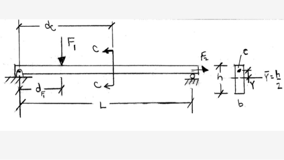
PROBLEM 2: 40% A 6 kN force is exerted on the frame which has the T cross sectio analyze the states of stress at a section taken at 800 mm from the point of n shown below. It is required to 1. Fo...
 PROBLEM 2: 40% A 6 kN force is exerted on the frame which has the T cross sectio analyze the states of stress at a section taken at 800 mm from the point of n shown below. It is required to 1. For the given T cross section, find the centroid and the area moment of inertia I,. 2. Draw the free body diagram of the free end of the frame and determine the interna loadings at the centroid of...
The member shown above has a W - shape cross séction. FIND a) draw the shear, moment and normal force diagram
 The member shown above has a W - shape cross séction. FINDa) draw the shear, moment and normal force diagramb) determine the absolute maximum bending stress in the beam and
draw the stress distribution over the cross section at this
location.c) draw the transverse shear stress distribution over the cross
section just to the right of point B.d) determine the state of stress that the loading produces at
point E and point F.e) Draw mohr's circle for state of stress at...
The member shown above has a W - shape cross séction. FINDa) draw the shear, moment and normal force diagramb) determine the absolute maximum bending stress in the beam and
draw the stress distribution over the cross section at this
location.c) draw the transverse shear stress distribution over the cross
section just to the right of point B.d) determine the state of stress that the loading produces at
point E and point F.e) Draw mohr's circle for state of stress at...
Just part c please Problem 1 GIVEN 4okum loomm comm 2.m The member shown above has a W-shape cross section. FIND a)...
 Just part c please
Problem 1 GIVEN 4okum loomm comm 2.m The member shown above has a W-shape cross section. FIND a) Draw the shear, moment and normal force diagram. b) Determine the absolute maximum bending stress in the beam and draw the stress distribution over the cross section at this location. o) Draw the transverse shear stress distribution over the cross section just to the right of point B. d) Determine the state of stress that the loading produces...
Just part c please
Problem 1 GIVEN 4okum loomm comm 2.m The member shown above has a W-shape cross section. FIND a) Draw the shear, moment and normal force diagram. b) Determine the absolute maximum bending stress in the beam and draw the stress distribution over the cross section at this location. o) Draw the transverse shear stress distribution over the cross section just to the right of point B. d) Determine the state of stress that the loading produces...
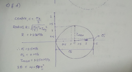
Use the Mohr circle shown on the right to answer the questions below. 20 B (a)...
 Use the Mohr circle shown on the right to answer the questions below. 20 B (a) Determine the state of stress (0.0, Ty) [ksi] depicted in the drawing of Mohr's circle. (b) Find the principle stresses (01. o:) [ksi) and the respective angles of principle stress (0.0,). (c) Calculate the maximum shear stress (Ima) [ksi) and the angles of maximum shear stress (0.1.0.). 20 40 60 01 σω) 20p --20 4 T|
(a) If the wide-flange beam shown in Figure Q4a is subjected to a shear of V = 23 kN
 (a) If the wide-flange beam shown in Figure Q4a is subjected to a shear of V = 23 kN i. Calculate the moment of inertia of the cross section about the neutral axis.ii. Determine the shear stress on the web at A.(b) The state of stress at a point is shown on the element in Figure Q4b. Determine graphically using Mohr's circle i. The principal stresses. ii. The orientation of the principal planes.iii. The maximum in-plane shear stress and average normal stress at...
a. Draw a free-body diagram for the beam shown above and derive expressions for the support...
 a. Draw a free-body diagram for the beam shown above and derive
expressions for the support reactions at A and B
b. Draw internal force (shear and bending moment) diagrams.
c. If a = 10 ft and M0 = 200 ft-lb, use the dimensions of the
beam cross-section, provided on the previous page, to compute the
maximum flexural and shear stresses on the beam cross-section.
d. If the allowable bending stress is 925 psi and the allowable
shear stress is...
a. Draw a free-body diagram for the beam shown above and derive
expressions for the support reactions at A and B
b. Draw internal force (shear and bending moment) diagrams.
c. If a = 10 ft and M0 = 200 ft-lb, use the dimensions of the
beam cross-section, provided on the previous page, to compute the
maximum flexural and shear stresses on the beam cross-section.
d. If the allowable bending stress is 925 psi and the allowable
shear stress is...
Problem #1 For the simply supported beam given below. E-200 GPa and u-o3. 18 kN 24...
 Problem #1 For the simply supported beam given below. E-200 GPa and u-o3. 18 kN 24 kN 2.4 m 4.0 m 1.8 m 150 mm 100 mm E.N.A 250 mm 200 mm Draw the shear diagram and the moment diagram For the location halfway between the right support and the 24 kN concentrated load, draw Mohr's circle for the stress states at points "a" "b", and "c" on the same axes a. b. c. For the location at midspan, draw...
Leaming Goal: To determine the shear stresses at specific locations in a beam due to an...
 Leaming Goal: To determine the shear stresses at specific locations in a beam due to an external loading. Beam ABC is subjected to the loading shown, where PB = 40.0 kN. The measurement corresponding to the half-length of the beam is a = 2.50 m. For the cross section shown, b = 50.0 mm, c= 125.0 mm, d = 125.0 mm, and e = 65.0 mm Point Dis located at the centroid of the cross section and point E is...
Problem 2 (20 pts): Mohr's Circle Use the Mohr circle shown on the right to answer...
 Problem 2 (20 pts): Mohr's Circle Use the Mohr circle shown on the right to answer the questions below. 20 B (a) Determine the state of stress (Ox, Oy, Txy) [ksi] depicted in the drawing of Mohr's circle. (b) Find the principle stresses (01, 02) [ksi] and the respective angles of principle stress (Opl, Op2). (c) Calculate the maximum shear stress (Tmax) [ksi] and the angles of maximum shear stress (Os1, 0:2). -20 20 40 60 02 0 01 [ksi]...
 2. Draw Shear Force and Bending Moment Diagram (use your preferred method). Determine Maximum Tensile and Compressive Stresses due to bending, state where on the beam these occur. For the mid-point between A and B, determine shear stress at neutral axis; 2" from the top of the flange; at the junction between web and flange and on the top of the flange for the cross-section. Plot of the bending stress and shear stress distribution diagram across the cross section of...
 PROBLEM 2: 40% A 6 kN force is exerted on the frame which has the T cross sectio analyze the states of stress at a section taken at 800 mm from the point of n shown below. It is required to 1. For the given T cross section, find the centroid and the area moment of inertia I,. 2. Draw the free body diagram of the free end of the frame and determine the interna loadings at the centroid of...
 Just part c please
Problem 1 GIVEN 4okum loomm comm 2.m The member shown above has a W-shape cross section. FIND a) Draw the shear, moment and normal force diagram. b) Determine the absolute maximum bending stress in the beam and draw the stress distribution over the cross section at this location. o) Draw the transverse shear stress distribution over the cross section just to the right of point B. d) Determine the state of stress that the loading produces...
Just part c please
Problem 1 GIVEN 4okum loomm comm 2.m The member shown above has a W-shape cross section. FIND a) Draw the shear, moment and normal force diagram. b) Determine the absolute maximum bending stress in the beam and draw the stress distribution over the cross section at this location. o) Draw the transverse shear stress distribution over the cross section just to the right of point B. d) Determine the state of stress that the loading produces...
 Use the Mohr circle shown on the right to answer the questions below. 20 B (a) Determine the state of stress (0.0, Ty) [ksi] depicted in the drawing of Mohr's circle. (b) Find the principle stresses (01. o:) [ksi) and the respective angles of principle stress (0.0,). (c) Calculate the maximum shear stress (Ima) [ksi) and the angles of maximum shear stress (0.1.0.). 20 40 60 01 σω) 20p --20 4 T|
 a. Draw a free-body diagram for the beam shown above and derive
expressions for the support reactions at A and B
b. Draw internal force (shear and bending moment) diagrams.
c. If a = 10 ft and M0 = 200 ft-lb, use the dimensions of the
beam cross-section, provided on the previous page, to compute the
maximum flexural and shear stresses on the beam cross-section.
d. If the allowable bending stress is 925 psi and the allowable
shear stress is...
a. Draw a free-body diagram for the beam shown above and derive
expressions for the support reactions at A and B
b. Draw internal force (shear and bending moment) diagrams.
c. If a = 10 ft and M0 = 200 ft-lb, use the dimensions of the
beam cross-section, provided on the previous page, to compute the
maximum flexural and shear stresses on the beam cross-section.
d. If the allowable bending stress is 925 psi and the allowable
shear stress is...
 Problem #1 For the simply supported beam given below. E-200 GPa and u-o3. 18 kN 24 kN 2.4 m 4.0 m 1.8 m 150 mm 100 mm E.N.A 250 mm 200 mm Draw the shear diagram and the moment diagram For the location halfway between the right support and the 24 kN concentrated load, draw Mohr's circle for the stress states at points "a" "b", and "c" on the same axes a. b. c. For the location at midspan, draw...
 Leaming Goal: To determine the shear stresses at specific locations in a beam due to an external loading. Beam ABC is subjected to the loading shown, where PB = 40.0 kN. The measurement corresponding to the half-length of the beam is a = 2.50 m. For the cross section shown, b = 50.0 mm, c= 125.0 mm, d = 125.0 mm, and e = 65.0 mm Point Dis located at the centroid of the cross section and point E is...
 Problem 2 (20 pts): Mohr's Circle Use the Mohr circle shown on the right to answer the questions below. 20 B (a) Determine the state of stress (Ox, Oy, Txy) [ksi] depicted in the drawing of Mohr's circle. (b) Find the principle stresses (01, 02) [ksi] and the respective angles of principle stress (Opl, Op2). (c) Calculate the maximum shear stress (Tmax) [ksi] and the angles of maximum shear stress (Os1, 0:2). -20 20 40 60 02 0 01 [ksi]...
Most questions answered within 3 hours.
-
Calculate the number density of argon gas at a temperature of
24C and a pressure of...
asked 2 hours ago -
Alternative
Classification
How to Estimate
Probabilities from Data? ( For continuous Attributes)
And How to generate...
asked 2 hours ago -
An explosion breaks a 20.0-kg object into three parts. The
object is initially moving at a...
asked 3 hours ago -
Calculate the approximate number of residues of Rubisco, which
is involved in carbon fixation in plants,...
asked 4 hours ago -
Other decisions about scientific claims can have a much broader
impact.ENERGYarrow-10x10.png, environment, health, security - all...
asked 4 hours ago -
I need to write a research paper and work cited about this
topic: The United States...
asked 5 hours ago -
Hello! I was wondering if I could have some help?
If the vapor pressure of carvone...
asked 5 hours ago -
An economist wants to estimate the mean per capita income (in
thousands of dollars) for a...
asked 6 hours ago -
What would be the input/output characteristic of a circuit
obtained by putting two of your 2's-complementers...
asked 6 hours ago -
In Drosophila, the transition from the syncytial blastoderm
stage to the cellular blastoderm stage is a...
asked 6 hours ago -
Project management question:
Name 3 different types of resources (hint: humans are one
type)
asked 6 hours ago -
Consider the following reaction: C 2H 2( g) + 2H 2( g) C 2H 6(
g)...
asked 6 hours ago