
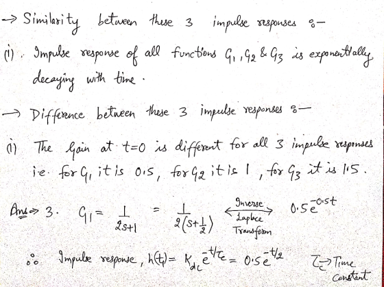
Homework Answers
Ans 1 :- Step response using MATLAB :-
![C:Program Files MATLAB MATLAB Production Server R2015a bin Command Window Figure 1 >G1=tf ([1], [2 11); >G2-tf ([2], [2 1]) >](http://img.homeworklib.com/images/1aadc451-331b-45fe-b882-0b6cb2630249.png?x-oss-process=image/resize,w_560)
 Ans
2 :- Impulse response using MATLAB :-
Ans
2 :- Impulse response using MATLAB :-
![C: Program Files MATLAB MATLAB Production Server R2015a bin Command Window AFigure 1 X >G1-tf ([1], [2 11) >G2=tf([2] , [2 1]](http://img.homeworklib.com/images/957b0d92-887a-423e-8beb-19d2c8cf20c0.png?x-oss-process=image/resize,w_560)


Feel free to ask if you have any query.Thank you.
Add Answer to:
Q4. 1 2 3 G 10 pts. Use MATLAB and plot the step response of the following systems G3 2s+1 figure. Gy on the same 2s+1...
Question 1: a) Use MATLAB, plot the step repose for the following transfer functions. 48 G(s)-...
 Question 1: a) Use MATLAB, plot the step repose for the following transfer functions. 48 G(s)- (8+6)(s+8) G(s)- 52 +2s + 18 18 Question 2: a) Using MATLAB, plot Bode log-magnitude and phase plot of (s+2)(8+5) G(S) - (s +3) ($2+2s +20) Question 3: Using MATLAB Sketch the root locus of the unity feedback system shown in the figure below: a) Give the values for all critical points of interest. b) Id the system ever unstable? If so, for what...
Use MATLAB to find the step response (plot) of a system with the following transfer function:...
 Use MATLAB to find the step response (plot) of a system with the following transfer function: G(S) = (s + 1) (s + 2) (s2 + 5s + 8) Copy and paste your MATLAB commands. Copy and paste the step response plot.
III.(6 pts.) A system is defined the following pole zero plot, where H(0)-10. a) Find the step response of the system.< Note: step response, not impulse response. b) (+3) Find the output, y()....
 III.(6 pts.) A system is defined the following pole zero plot, where H(0)-10. a) Find the step response of the system.< Note: step response, not impulse response. b) (+3) Find the output, y(). when the input is x()-8(0)-e) H(O) 10 -1 -2
III.(6 pts.) A system is defined the following pole zero plot, where H(0)-10. a) Find the step response of the system.
III.(6 pts.) A system is defined the following pole zero plot, where H(0)-10. a) Find the step response of the system.< Note: step response, not impulse response. b) (+3) Find the output, y(). when the input is x()-8(0)-e) H(O) 10 -1 -2
III.(6 pts.) A system is defined the following pole zero plot, where H(0)-10. a) Find the step response of the system.
3. Impulse Response and Step Response. (25 pts) Consider the following LTI systems: • T1: Has...
 3. Impulse Response and Step Response. (25 pts) Consider the following LTI systems: • T1: Has input-output relationship yı(t) = -X1(t – 5) 1<t<4 • T2: Has impulse response hz(t) = { therwise • T3: Has step response s3(t) = -4u(t + 3) • T4: Has step response s4(t) = -tu(t) (a) (5 pts) What is the impulse response hi(t) of system Tj? (b) (10 pts) What is the step response sz(t) of system T2? Write it in terms of...
X(s) U(s) s2+ 10s+625 625 b. Plot/find the time response of this system using MATLAB when...
 X(s) U(s) s2+ 10s+625 625 b. Plot/find the time response of this system using MATLAB when subjected to the input signal in Figure 2. Assume t -O, t2 -10-9, and A - 10 Hint: What can the input signal be approximated as? Use the approximation. Plot the response for at least 1 second. 1) Provide the plot. You do not need to print an answer to the hint. 0 Figure 2. Input u(t) c. Redo part b using the transfer...
PLEASE USE MATLAB TO ANSWER ALL OF THE PARTS. PROVIDE MATLAB CODE FOR EACH OF THE...
 PLEASE USE MATLAB TO ANSWER ALL OF THE
PARTS.
PROVIDE MATLAB CODE FOR EACH OF THE PART.
PUT THE ANSWER IN A BOX.
Consider the unity feedback system depicted in Figure 1 G(s) R(s) 50K s(s + a) Figure 1 1. Determine the system's closed loop transfer function. 2. Plot the system's step response for K=10 and: • a= 2 • a=5 • a= 10 3. What happens to the system's response as a increases? Justify your answer. 4. In...
PLEASE USE MATLAB TO ANSWER ALL OF THE
PARTS.
PROVIDE MATLAB CODE FOR EACH OF THE PART.
PUT THE ANSWER IN A BOX.
Consider the unity feedback system depicted in Figure 1 G(s) R(s) 50K s(s + a) Figure 1 1. Determine the system's closed loop transfer function. 2. Plot the system's step response for K=10 and: • a= 2 • a=5 • a= 10 3. What happens to the system's response as a increases? Justify your answer. 4. In...
Matlab help 1) Given the functions x1()= tu()-tuft-1) and X2(t)=10e-5,11(), do the following: 1. Plotx,(t) and x2(0) using MATLAB 2. Use MATLAB to find and plot x(0=x:@*.x2(t), where * denotes co...
 Matlab help
1) Given the functions x1()= tu()-tuft-1) and X2(t)=10e-5,11(), do the following: 1. Plotx,(t) and x2(0) using MATLAB 2. Use MATLAB to find and plot x(0=x:@*.x2(t), where * denotes convolution. 3. Find x(t)=x;()*X2(1) by hand using Laplace transforms. 4. Plot the result of part 3 in MATLAB and compare it to that found in part 2. 2) Given the transfer function shown below, do the following: 1. Find the system's impulse response and plot it using MATLAB 2. Repeat...
Matlab help
1) Given the functions x1()= tu()-tuft-1) and X2(t)=10e-5,11(), do the following: 1. Plotx,(t) and x2(0) using MATLAB 2. Use MATLAB to find and plot x(0=x:@*.x2(t), where * denotes convolution. 3. Find x(t)=x;()*X2(1) by hand using Laplace transforms. 4. Plot the result of part 3 in MATLAB and compare it to that found in part 2. 2) Given the transfer function shown below, do the following: 1. Find the system's impulse response and plot it using MATLAB 2. Repeat...
Consider the system:y[n]-0.5y[n-1]-0.25y[n-2]=x[n]+2x[n-1]+x[n-2] • Plot, using MATLAB, the impulse and step responses of the system. Highlight...
Consider the system:y[n]-0.5y[n-1]-0.25y[n-2]=x[n]+2x[n-1]+x[n-2] • Plot, using MATLAB, the impulse and step responses of the system. Highlight the response characteristics in your plots • Assume initial conditions y(-1) = 1, y(-2) = 0 and that the input signal to the system is a discrete-time unit step. Determine the formula for the Z-transform of the solution, Y(z). Subsequently, determine the formula for the solution, y[n], itself.
1) Use Simulink to plot the unit step response of the following block diagram for K-1, 2, 5 and f...
 1) Use Simulink to plot the unit step response of the following block diagram for K-1, 2, 5 and find Mp, tp, ts from the figure. (116s2 +1187s+8260) K(s) K controller plant R(s) K(s) G(s) Y(s) 2) Find the state variable representation of closed loop system of (1) by using Simulink.
1) Use Simulink to plot the unit step response of the following block diagram for K-1, 2, 5 and find Mp, tp, ts from the figure. (116s2 +1187s+8260) K(s)...
1) Use Simulink to plot the unit step response of the following block diagram for K-1, 2, 5 and find Mp, tp, ts from the figure. (116s2 +1187s+8260) K(s) K controller plant R(s) K(s) G(s) Y(s) 2) Find the state variable representation of closed loop system of (1) by using Simulink.
1) Use Simulink to plot the unit step response of the following block diagram for K-1, 2, 5 and find Mp, tp, ts from the figure. (116s2 +1187s+8260) K(s)...
2. then design the LF components Ri. R2,and C to produce and plot with Matlab the following step ...
 2. then design the LF components Ri. R2,and C to produce and plot with Matlab the following step responses by the PLL a. overdamped, b. underdamped, c. critically damped; 3. calculate the phase step response's following parameters: a. b. c. d. rise time T peak time Tp (if applicable) percent overshoot %OS(if applicable) settling time T, c) calculate the steady state phase error lim0e(t) for both PLL types, and draw conclusions whether your PLL can track the: i. incoming signal's...
 Question 1: a) Use MATLAB, plot the step repose for the following transfer functions. 48 G(s)- (8+6)(s+8) G(s)- 52 +2s + 18 18 Question 2: a) Using MATLAB, plot Bode log-magnitude and phase plot of (s+2)(8+5) G(S) - (s +3) ($2+2s +20) Question 3: Using MATLAB Sketch the root locus of the unity feedback system shown in the figure below: a) Give the values for all critical points of interest. b) Id the system ever unstable? If so, for what...
 Use MATLAB to find the step response (plot) of a system with the following transfer function: G(S) = (s + 1) (s + 2) (s2 + 5s + 8) Copy and paste your MATLAB commands. Copy and paste the step response plot.
 III.(6 pts.) A system is defined the following pole zero plot, where H(0)-10. a) Find the step response of the system.< Note: step response, not impulse response. b) (+3) Find the output, y(). when the input is x()-8(0)-e) H(O) 10 -1 -2
III.(6 pts.) A system is defined the following pole zero plot, where H(0)-10. a) Find the step response of the system.
III.(6 pts.) A system is defined the following pole zero plot, where H(0)-10. a) Find the step response of the system.< Note: step response, not impulse response. b) (+3) Find the output, y(). when the input is x()-8(0)-e) H(O) 10 -1 -2
III.(6 pts.) A system is defined the following pole zero plot, where H(0)-10. a) Find the step response of the system.
 3. Impulse Response and Step Response. (25 pts) Consider the following LTI systems: • T1: Has input-output relationship yı(t) = -X1(t – 5) 1<t<4 • T2: Has impulse response hz(t) = { therwise • T3: Has step response s3(t) = -4u(t + 3) • T4: Has step response s4(t) = -tu(t) (a) (5 pts) What is the impulse response hi(t) of system Tj? (b) (10 pts) What is the step response sz(t) of system T2? Write it in terms of...
 X(s) U(s) s2+ 10s+625 625 b. Plot/find the time response of this system using MATLAB when subjected to the input signal in Figure 2. Assume t -O, t2 -10-9, and A - 10 Hint: What can the input signal be approximated as? Use the approximation. Plot the response for at least 1 second. 1) Provide the plot. You do not need to print an answer to the hint. 0 Figure 2. Input u(t) c. Redo part b using the transfer...
 PLEASE USE MATLAB TO ANSWER ALL OF THE
PARTS.
PROVIDE MATLAB CODE FOR EACH OF THE PART.
PUT THE ANSWER IN A BOX.
Consider the unity feedback system depicted in Figure 1 G(s) R(s) 50K s(s + a) Figure 1 1. Determine the system's closed loop transfer function. 2. Plot the system's step response for K=10 and: • a= 2 • a=5 • a= 10 3. What happens to the system's response as a increases? Justify your answer. 4. In...
PLEASE USE MATLAB TO ANSWER ALL OF THE
PARTS.
PROVIDE MATLAB CODE FOR EACH OF THE PART.
PUT THE ANSWER IN A BOX.
Consider the unity feedback system depicted in Figure 1 G(s) R(s) 50K s(s + a) Figure 1 1. Determine the system's closed loop transfer function. 2. Plot the system's step response for K=10 and: • a= 2 • a=5 • a= 10 3. What happens to the system's response as a increases? Justify your answer. 4. In...
 Matlab help
1) Given the functions x1()= tu()-tuft-1) and X2(t)=10e-5,11(), do the following: 1. Plotx,(t) and x2(0) using MATLAB 2. Use MATLAB to find and plot x(0=x:@*.x2(t), where * denotes convolution. 3. Find x(t)=x;()*X2(1) by hand using Laplace transforms. 4. Plot the result of part 3 in MATLAB and compare it to that found in part 2. 2) Given the transfer function shown below, do the following: 1. Find the system's impulse response and plot it using MATLAB 2. Repeat...
Matlab help
1) Given the functions x1()= tu()-tuft-1) and X2(t)=10e-5,11(), do the following: 1. Plotx,(t) and x2(0) using MATLAB 2. Use MATLAB to find and plot x(0=x:@*.x2(t), where * denotes convolution. 3. Find x(t)=x;()*X2(1) by hand using Laplace transforms. 4. Plot the result of part 3 in MATLAB and compare it to that found in part 2. 2) Given the transfer function shown below, do the following: 1. Find the system's impulse response and plot it using MATLAB 2. Repeat...
 1) Use Simulink to plot the unit step response of the following block diagram for K-1, 2, 5 and find Mp, tp, ts from the figure. (116s2 +1187s+8260) K(s) K controller plant R(s) K(s) G(s) Y(s) 2) Find the state variable representation of closed loop system of (1) by using Simulink.
1) Use Simulink to plot the unit step response of the following block diagram for K-1, 2, 5 and find Mp, tp, ts from the figure. (116s2 +1187s+8260) K(s)...
1) Use Simulink to plot the unit step response of the following block diagram for K-1, 2, 5 and find Mp, tp, ts from the figure. (116s2 +1187s+8260) K(s) K controller plant R(s) K(s) G(s) Y(s) 2) Find the state variable representation of closed loop system of (1) by using Simulink.
1) Use Simulink to plot the unit step response of the following block diagram for K-1, 2, 5 and find Mp, tp, ts from the figure. (116s2 +1187s+8260) K(s)...
 2. then design the LF components Ri. R2,and C to produce and plot with Matlab the following step responses by the PLL a. overdamped, b. underdamped, c. critically damped; 3. calculate the phase step response's following parameters: a. b. c. d. rise time T peak time Tp (if applicable) percent overshoot %OS(if applicable) settling time T, c) calculate the steady state phase error lim0e(t) for both PLL types, and draw conclusions whether your PLL can track the: i. incoming signal's...
Most questions answered within 3 hours.
-
4. Without doing any calculations, predict whether the observed
∆T would increase, decrease or remain the...
asked 1 hour ago -
Based on the range, which of the following sets of scores has
the greatest variability? 3,...
asked 2 hours ago -
Ripples in a pond travel at a velocity of 3 m/s with one peak
passing a...
asked 2 hours ago -
A man stands on the roof of a building of height 13.0 mm and
throws a...
asked 2 hours ago -
The extent to which assets are financed by borrowed funds and
other liabilities is indicated by:...
asked 3 hours ago -
Explain in detail
Germany is the fifth largest economy
explain what goods and services Germany specializes...
asked 3 hours ago -
The density of platinum is 21.45 g/mL. If a cube of platinum
with a mass of...
asked 3 hours ago -
Accounts Receivable
Sales
A/R Posting
Extended Sales Invoice
Packing Slip
Compare invoice to packing slip 2...
asked 3 hours ago -
Michaella, age 23, is a full-time law student and is claimed by
her parents as a...
asked 3 hours ago -
Why are polymers not typically casted into products?
asked 3 hours ago -
When rolling a die 129 times, what is the probability of rolling
a 6 no more...
asked 4 hours ago -
4. A call option currently sells for $7.75. It has a strike
price of $85 and...
asked 4 hours ago