
Homework Answers


Add Answer to:
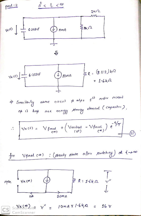
For the circuit below calculate and sketch waveform of the voltage v(t), both for t <...
The input voltage waveform (Vin) t in is shown below along with the circuit. The voltage-controlled...
 The input voltage waveform (Vin) t in is shown below along with
the circuit. The voltage-controlled switch S1 closes when the
output voltage Vc (t) goes positive at t=0 and opens when Vc (t)
goes negative at t=5 µs. Assume that Vin(t) in has been at 10 V for
t<0 for a very long time..
3. (15 marks) The input voltage waveform Vin(t) is shown below along with the circuit. The voltage- controlled switch S, closes when the output voltage...
The input voltage waveform (Vin) t in is shown below along with
the circuit. The voltage-controlled switch S1 closes when the
output voltage Vc (t) goes positive at t=0 and opens when Vc (t)
goes negative at t=5 µs. Assume that Vin(t) in has been at 10 V for
t<0 for a very long time..
3. (15 marks) The input voltage waveform Vin(t) is shown below along with the circuit. The voltage- controlled switch S, closes when the output voltage...
Question 5: Sketch the output waveform V, and calculate the hysteresis voltage Vy for the following...
 Question 5: Sketch the output waveform V, and calculate the hysteresis voltage Vy for the following circuit a) +15 V 10 sin ot Volto VO -15 V R2 R w 10 kΩ 30 kΩ b) If the 10 k 2 resistor in (a) above is not grounded, but is instead connected to DC voltage source of +7V, sketch V, and calculate the new value of V.
Problem 13. The voltage across a 6 uF capacitor is given by the waveform shown below....
 Problem 13. The voltage across a 6 uF capacitor is given by the waveform shown below. Plot the current through the capacitor. A v() (V) 10 0.S t (ms -10- Problem 14 Find Rt in the circuit shown below in order to achieve maximum power transfer. 2 k2 RL 12 V+
How would you find v(t) ? 1. Solve for the voltage v(t) in the circuit shown...
 How would you find v(t) ?
1. Solve for the voltage v(t) in the circuit shown below when t = 0.73 ms. The voltage source is e(t) = 8 Vu(t), where u(t) is the unit step function. The component values are: R1 = 3 k.2, R2 = 4k.2. R3 = 2 k2, R4 = 10 k.2, R; = 1 k.2 and C = 0.22uF. RA w R1 w R2 e(t) ( R57 Ra} V(t) v(t) =
How would you find v(t) ?
1. Solve for the voltage v(t) in the circuit shown below when t = 0.73 ms. The voltage source is e(t) = 8 Vu(t), where u(t) is the unit step function. The component values are: R1 = 3 k.2, R2 = 4k.2. R3 = 2 k2, R4 = 10 k.2, R; = 1 k.2 and C = 0.22uF. RA w R1 w R2 e(t) ( R57 Ra} V(t) v(t) =
Problem 4. In this circuit, the initial voltage is 0 V for both 1 uF and...
 Problem 4. In this circuit, the initial voltage is 0 V for both 1 uF and 3 uF capacitors. If the switch is connected at t=0 s, what is the value of V1 (0)? B_ (20 points) A. 3V B. 1 V C. Oy D. None of the above is correct - 20
Ri Sw Sw2R (a) Circuit Swi Closed + Open T t (ms) 10 20 30 40...
 Ri Sw Sw2R (a) Circuit Swi Closed + Open T t (ms) 10 20 30 40 50 Sw2 Closed (ms) 10 20 30 40 50 Figure m5.3 Voltage waveform for Problem m5.3. m5.3 Response of the RC Circuit: Figure m5.3(a) shows a resistor-capacitor circuit with a pair of switches and Fig. m5.3(b) shows the switch opening-closing behavior a function of time. The initial capacitor voltage is as -9 V. Component values are R1-10k. R2-3.3 kg2. (a) Determine the equation that...
Question 2: (20 pts.) In the circuit below E =12V, R1 = R2 = 10 ohm,...
 Question 2: (20 pts.) In the circuit below E =12V, R1 = R2 = 10 ohm, and C = 4 uF. Initially the switch Sis open. At t=0 the switch S is closed. (a) What is the current i, through R, at t= 0 and t = 00 ? (b) Draw a qualitative graph of the potential drop V, through R. from t=0 to t=00. (c) When C is fully charged, switch S is opened. What is the current iz...
PART B: 04 Sketch graph for sin waveform and cosine waveform for AC voltage and AC...
 PART B: 04 Sketch graph for sin waveform and cosine waveform for AC voltage and AC current. (4 marks) (b) Obtain the energy stored in each capacitor in Figure Q4(b) under DC conditions. (6 marks) (c) Determine the current through a 200 uF capacitor whose voltage is shown in Figure Q4(c). Sketch graph for current, I versus time, t. (10 marks) 2 mF Η Λ 2 ΚΩ 5 ΚΩ ΛΜ 6 mA 3 ΚΩ ΑΛΛ 4 ΚΩ 4 mE Figure...
PI : For circuit below v-20 V and R,-8 Ohm and R2-2 Ohm. Calculate voltage and...
 PI : For circuit below v-20 V and R,-8 Ohm and R2-2 Ohm. Calculate voltage and power loss in each resistor in the circuit. (Use voltage division and P = (voltage*voltage) resistance)- You cannot use KVL, KCL or Ohms law) Ri R2 P2: For circuit below i = 50 A and R1 = 15 Ohm and R2 = 10 Ohm. Calculate current and power loss in each resistor in the circuit. (Use current division and P - (current*current) resistance) You...
For the next set of questions, consider the following circuit. The switch has been open for...
 For the next set of questions, consider the following circuit. The switch has been open for a long time. At t=0, it is closed. t=0 11 R1 3 1 3 C c IL R2 3 V = Assume the following values: 11=5mA 12=10mA R1=2K R2=2k L1=10mH C1 = luF Find the following: a) 11(0), the initial current through the inductor (in mA): b) The final current thru the inductor after the switch has been closed for a long time (in...
 The input voltage waveform (Vin) t in is shown below along with
the circuit. The voltage-controlled switch S1 closes when the
output voltage Vc (t) goes positive at t=0 and opens when Vc (t)
goes negative at t=5 µs. Assume that Vin(t) in has been at 10 V for
t<0 for a very long time..
3. (15 marks) The input voltage waveform Vin(t) is shown below along with the circuit. The voltage- controlled switch S, closes when the output voltage...
The input voltage waveform (Vin) t in is shown below along with
the circuit. The voltage-controlled switch S1 closes when the
output voltage Vc (t) goes positive at t=0 and opens when Vc (t)
goes negative at t=5 µs. Assume that Vin(t) in has been at 10 V for
t<0 for a very long time..
3. (15 marks) The input voltage waveform Vin(t) is shown below along with the circuit. The voltage- controlled switch S, closes when the output voltage...
 Question 5: Sketch the output waveform V, and calculate the hysteresis voltage Vy for the following circuit a) +15 V 10 sin ot Volto VO -15 V R2 R w 10 kΩ 30 kΩ b) If the 10 k 2 resistor in (a) above is not grounded, but is instead connected to DC voltage source of +7V, sketch V, and calculate the new value of V.
 Problem 13. The voltage across a 6 uF capacitor is given by the waveform shown below. Plot the current through the capacitor. A v() (V) 10 0.S t (ms -10- Problem 14 Find Rt in the circuit shown below in order to achieve maximum power transfer. 2 k2 RL 12 V+
 How would you find v(t) ?
1. Solve for the voltage v(t) in the circuit shown below when t = 0.73 ms. The voltage source is e(t) = 8 Vu(t), where u(t) is the unit step function. The component values are: R1 = 3 k.2, R2 = 4k.2. R3 = 2 k2, R4 = 10 k.2, R; = 1 k.2 and C = 0.22uF. RA w R1 w R2 e(t) ( R57 Ra} V(t) v(t) =
How would you find v(t) ?
1. Solve for the voltage v(t) in the circuit shown below when t = 0.73 ms. The voltage source is e(t) = 8 Vu(t), where u(t) is the unit step function. The component values are: R1 = 3 k.2, R2 = 4k.2. R3 = 2 k2, R4 = 10 k.2, R; = 1 k.2 and C = 0.22uF. RA w R1 w R2 e(t) ( R57 Ra} V(t) v(t) =
 Problem 4. In this circuit, the initial voltage is 0 V for both 1 uF and 3 uF capacitors. If the switch is connected at t=0 s, what is the value of V1 (0)? B_ (20 points) A. 3V B. 1 V C. Oy D. None of the above is correct - 20
 Ri Sw Sw2R (a) Circuit Swi Closed + Open T t (ms) 10 20 30 40 50 Sw2 Closed (ms) 10 20 30 40 50 Figure m5.3 Voltage waveform for Problem m5.3. m5.3 Response of the RC Circuit: Figure m5.3(a) shows a resistor-capacitor circuit with a pair of switches and Fig. m5.3(b) shows the switch opening-closing behavior a function of time. The initial capacitor voltage is as -9 V. Component values are R1-10k. R2-3.3 kg2. (a) Determine the equation that...
 Question 2: (20 pts.) In the circuit below E =12V, R1 = R2 = 10 ohm, and C = 4 uF. Initially the switch Sis open. At t=0 the switch S is closed. (a) What is the current i, through R, at t= 0 and t = 00 ? (b) Draw a qualitative graph of the potential drop V, through R. from t=0 to t=00. (c) When C is fully charged, switch S is opened. What is the current iz...
 PART B: 04 Sketch graph for sin waveform and cosine waveform for AC voltage and AC current. (4 marks) (b) Obtain the energy stored in each capacitor in Figure Q4(b) under DC conditions. (6 marks) (c) Determine the current through a 200 uF capacitor whose voltage is shown in Figure Q4(c). Sketch graph for current, I versus time, t. (10 marks) 2 mF Η Λ 2 ΚΩ 5 ΚΩ ΛΜ 6 mA 3 ΚΩ ΑΛΛ 4 ΚΩ 4 mE Figure...
 PI : For circuit below v-20 V and R,-8 Ohm and R2-2 Ohm. Calculate voltage and power loss in each resistor in the circuit. (Use voltage division and P = (voltage*voltage) resistance)- You cannot use KVL, KCL or Ohms law) Ri R2 P2: For circuit below i = 50 A and R1 = 15 Ohm and R2 = 10 Ohm. Calculate current and power loss in each resistor in the circuit. (Use current division and P - (current*current) resistance) You...
 For the next set of questions, consider the following circuit. The switch has been open for a long time. At t=0, it is closed. t=0 11 R1 3 1 3 C c IL R2 3 V = Assume the following values: 11=5mA 12=10mA R1=2K R2=2k L1=10mH C1 = luF Find the following: a) 11(0), the initial current through the inductor (in mA): b) The final current thru the inductor after the switch has been closed for a long time (in...
Most questions answered within 3 hours.
-
Consider a 3m x 3m window in a house. The thermal conductivity
is reported to be...
asked 7 minutes ago -
Why has California been the favorite destination of large number
of secondary migrants?
asked 40 minutes ago -
Do not neglect the old for the new. The existing business must
not lose priority simply...
asked 3 hours ago -
Kylie is a single mom with two dependent children,
Tanner, age 7 and Olivia, age 11....
asked 5 hours ago -
Phosphorous + bromine = phosphorous tribromide. If 35.0 g of
bromine are reacted and 27.9 grams...
asked 6 hours ago -
Derive the long wavelength limit of the Planck energy density
distribution
asked 6 hours ago -
Calculate the pH of each of the following solutions.
0.50 M HBr
3.1×10⁻⁴ M KOH
4.2×10⁻⁵...
asked 9 hours ago -
For the year ended December 31, Depot Max’s cost of merchandise
sold was $85,600. Inventory at the...
asked 9 hours ago -
Week 10 - Professional Memo Assignment
Professional Memo Assignment
Your mission for this week, should you...
asked 10 hours ago -
Write a Python program that stores the data for each
player on the team, and it...
asked 10 hours ago -
In
the last 3 months, mike never knows when he is going to get his
allowance...
asked 10 hours ago -
Is Ca(OH)2 a Bronsted base, Lewis base, or both? Why?
asked 10 hours ago