

B G F Figure 2
Homework Answers

Add Answer to:
b) An 80MVA, 11kV synchronous generator with a sub transient reactance j0.125pu is connected to each...
b) An 80MVA, 11kV synchronous generator with a sub transient reactance j0.125pu is connected to each...
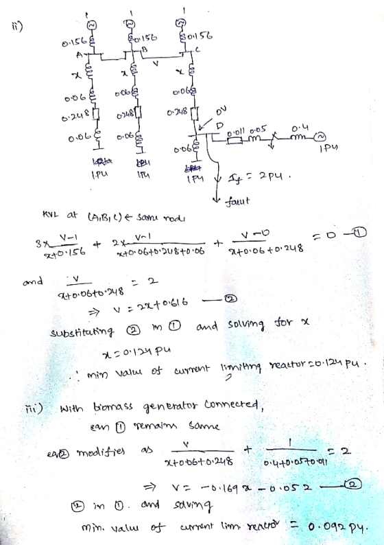
 b) An 80MVA, 11kV synchronous generator with a sub transient reactance j0.125pu is connected to each of three busbars labelled A, B and C in Figure 2. Three equal current limiting reactors (100MVA, 11kV) are connected in series with the feeders. The main busbars supply secondary busbars (E, F and G) through a line of reactance j2.70 and 100MVA, 11kV/33kV j0.06pu transformers at both ends Busbar D is commected at the 33kv side of the transformer at G to facilitate...
Question 2 A 60 Hz synchronous generator with Xd 0.2 pu transient reactance is connected to...
 Question 2 A 60 Hz synchronous generator with Xd 0.2 pu transient reactance is connected to an infinite us through a transformer and the transmisiones as shown in the Figure. All system reactances are marked on the diagram and are expressed on a common MVA base. The generator dies a power of Auto busbar 1. The magnitude of the generator's excitation voltage e'is 12 pu, and the infinite bus voltage is -1.00u. If a 3-phase fault occurs at the middle...
3. A 200 MVA, 20 kV, 60 Hz Y-connected solidly grounded three phase synchronous generator connect...
 3. A 200 MVA, 20 kV, 60 Hz Y-connected solidly grounded three phase synchronous generator connected through a 200 MVA 20/138 KV Y-Y transformer to a 138 kV transmission line. The generator reactances to the machine's own base are X-1.10 Both of the transformers Y connections are solidly grounded and its positive, negative and zero sequence series resitances are all 0.10 pu. a. What is the voltage at the terminals of the generator during the sub transient period if a...
Question3 3000 kVA / 0.09 p.u. Alternators 2 40004VA 0.12 p.u 6kV Busbars 4000 LVA 0.05 p.. Transmission Lines Lin...
 Question3 3000 kVA / 0.09 p.u. Alternators 2 40004VA 0.12 p.u 6kV Busbars 4000 LVA 0.05 p.. Transmission Lines Lines 4000 kV 0.05 p.ย. Step-Up Transformers 5000 kVA 5000 kVA 0.06 р.u. 0.06 p.u. 11 kV Basbars -150 kVA 0.05 pu. Secondary feeder line Step-Down 1500 kVA 0.03 p.u 415 V Busbars Fault Point Figure Q3 Figure Q3 shows a power system comprising two three phase alternators supplying 6 kV busbars. I wo paralilel transmission lines fed from these busbars...
LOAD 90MW 0.8 p.f (lag) ZONEC Te 33kV/130kV SOMVA X=15% ZONE B ZONE D ZONE A...
 LOAD 90MW 0.8 p.f (lag) ZONEC Te 33kV/130kV SOMVA X=15% ZONE B ZONE D ZONE A (12V) j150 116/122ky SOMVA X-0.12 130kV/11kV 100MVA X=10% 10 BV 100MVA X0.10 10.8V 150MVA X+0.12 1300 Te Td 11kv/132kv 100MVA X-0.15 ZONE E 130kV/11kV SOMVA X 13% Figure 1 Figure 1 shows the schematic diagram of a three-phase radial transmission system. Using a base of 100 MVA and voltage reference as indicated at ZONE A, (a) Identify the new voltage base in ZONE B,...
A 50 Hz, 250 MVA synchronous generator having inertia constant H=5 MJ/MVA is connected to an infinite bus through trans...
 A 50 Hz, 250 MVA synchronous generator having inertia constant H=5 MJ/MVA is connected to an infinite bus through transformer and transmission line as shown below. The transformer reactance is based on 500 MVA, while the other impedances are based on the generator MVA Infinite bus 1 2 3 XL 0.1 pu - oto G1 V= 1.0 pu X 0.1 pu Xd = 0.3 pu at 500 MVA The generator is delivering 0.8 of full load current at a power...
 b) An 80MVA, 11kV synchronous generator with a sub transient reactance j0.125pu is connected to each of three busbars labelled A, B and C in Figure 2. Three equal current limiting reactors (100MVA, 11kV) are connected in series with the feeders. The main busbars supply secondary busbars (E, F and G) through a line of reactance j2.70 and 100MVA, 11kV/33kV j0.06pu transformers at both ends Busbar D is commected at the 33kv side of the transformer at G to facilitate...
 Question 2 A 60 Hz synchronous generator with Xd 0.2 pu transient reactance is connected to an infinite us through a transformer and the transmisiones as shown in the Figure. All system reactances are marked on the diagram and are expressed on a common MVA base. The generator dies a power of Auto busbar 1. The magnitude of the generator's excitation voltage e'is 12 pu, and the infinite bus voltage is -1.00u. If a 3-phase fault occurs at the middle...
 3. A 200 MVA, 20 kV, 60 Hz Y-connected solidly grounded three phase synchronous generator connected through a 200 MVA 20/138 KV Y-Y transformer to a 138 kV transmission line. The generator reactances to the machine's own base are X-1.10 Both of the transformers Y connections are solidly grounded and its positive, negative and zero sequence series resitances are all 0.10 pu. a. What is the voltage at the terminals of the generator during the sub transient period if a...
 Question3 3000 kVA / 0.09 p.u. Alternators 2 40004VA 0.12 p.u 6kV Busbars 4000 LVA 0.05 p.. Transmission Lines Lines 4000 kV 0.05 p.ย. Step-Up Transformers 5000 kVA 5000 kVA 0.06 р.u. 0.06 p.u. 11 kV Basbars -150 kVA 0.05 pu. Secondary feeder line Step-Down 1500 kVA 0.03 p.u 415 V Busbars Fault Point Figure Q3 Figure Q3 shows a power system comprising two three phase alternators supplying 6 kV busbars. I wo paralilel transmission lines fed from these busbars...
 LOAD 90MW 0.8 p.f (lag) ZONEC Te 33kV/130kV SOMVA X=15% ZONE B ZONE D ZONE A (12V) j150 116/122ky SOMVA X-0.12 130kV/11kV 100MVA X=10% 10 BV 100MVA X0.10 10.8V 150MVA X+0.12 1300 Te Td 11kv/132kv 100MVA X-0.15 ZONE E 130kV/11kV SOMVA X 13% Figure 1 Figure 1 shows the schematic diagram of a three-phase radial transmission system. Using a base of 100 MVA and voltage reference as indicated at ZONE A, (a) Identify the new voltage base in ZONE B,...
 A 50 Hz, 250 MVA synchronous generator having inertia constant H=5 MJ/MVA is connected to an infinite bus through transformer and transmission line as shown below. The transformer reactance is based on 500 MVA, while the other impedances are based on the generator MVA Infinite bus 1 2 3 XL 0.1 pu - oto G1 V= 1.0 pu X 0.1 pu Xd = 0.3 pu at 500 MVA The generator is delivering 0.8 of full load current at a power...
Most questions answered within 3 hours.
-
The free energy change for the following reaction at 25 °C, when
[Sn2+] = 1.17 M...
asked 16 minutes ago -
An MNE is this kind of industry when competition in one country
is essentially independent of...
asked 1 hour ago -
. For this set of questions, determine what
proportion of a normal distribution is located betweeneach...
asked 2 hours ago -
A college student is employed as a door-to-door newspaper
salesman. Historical data suggests that the student...
asked 3 hours ago -
MATLAB HW 11 problem using Switch Case and Input commands
Write a script file that calculates...
asked 3 hours ago -
Considering gravitational time dilation, calculate the time that
passes in Earth’s surface while 1 hour passes...
asked 3 hours ago -
Minitab Problem: Take the Lake Hume June rainfall data and find
use the processes outlined in...
asked 4 hours ago -
X Company is trying to decide whether to continue using old
equipment to make Product A...
asked 4 hours ago -
IN PYTHON ONLY !! Program 2: Re-work
program #5 (WeeklyHours) from the previous assignment such that...
asked 5 hours ago -
The average length of time between arrivals at a turnpike
toll-booth is 26 seconds. What is...
asked 6 hours ago -
(a) A piston at 6.1 atm contains a gas that occupies a volume of
3.5 L....
asked 8 hours ago -
Please answer true or false. Words
cannot be changed or added in to make it true...
asked 8 hours ago