
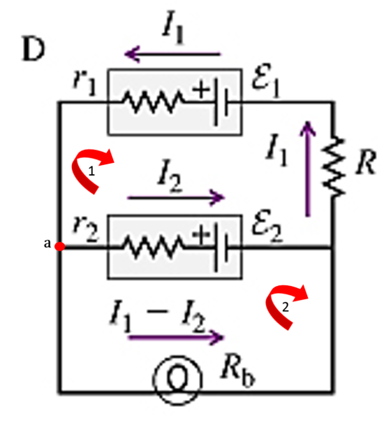
Using Kirchhoff's junction rule, determine which one of the following four diagrams would be the appropriate one to use for solving this problem.

Homework Answers


Solution
Part a)
For Figure A, applying Kirchhoff's junction rule we have that:
Therefore, figure A is not correct.
For figure B, applying Kirchhoff's junction rule we have that:
therefore, figure B is not correct
For figure C, applying Kirchhoff's junction rule we have that:
therefore, figure C is not correct.
For figure D, applying Kirchhoff's junction rule we have that:
Therefore, the correct figure is figure D:

Part b)
Applying Kirchhoff's loop rule at loop 1 we have:
but:
and
Replacing (2) and (3) into equation (1):
or
Simillarly, applying Kirchhoff's loop rule at loop 2 we have:
Replacing (3) into equation (6):
Grouping equations (5) and (7) we have:
Solving the system for
we
have:


Add Answer to:
Part A
Using Kirchhoff's junction rule, determine which one of the
following four diagrams would be...
How do I calculate the “calculated current flowing through each resistor using Kirchhoffs junction rule and...
 How do I calculate the
“calculated current flowing through each resistor using Kirchhoffs
junction rule and the measured values”? Please show your work.
Thank you!
Old Dominion University Physics 112 & 232 Lab 2. Use the EXTECH Digital M measure the individual resi "orange, black, brown" band Turn on the DMM and turn 2000 Ω position. 2 V 1.5 V Using wire leads with ab and alligator clip on opp banana plug end of a red wi 2) jack, and...
How do I calculate the
“calculated current flowing through each resistor using Kirchhoffs
junction rule and the measured values”? Please show your work.
Thank you!
Old Dominion University Physics 112 & 232 Lab 2. Use the EXTECH Digital M measure the individual resi "orange, black, brown" band Turn on the DMM and turn 2000 Ω position. 2 V 1.5 V Using wire leads with ab and alligator clip on opp banana plug end of a red wi 2) jack, and...
please help with problems 7 and 8, I am extremely confused! Part 2: Kirchhoff's Rules For...
 please help with problems 7 and 8, I am extremely
confused!
Part 2: Kirchhoff's Rules For the circuit shown below, the directions of the currents through the circuit elements has been chosen arbitrarily. Using Kirchhoff's rules, you will determine the actual currents through the circuit elements. (Yes, this circuit could be analyzed using equivalent resistance, but don't do it that way.) R1: 752 Kirchhoff's Junction Rule 4) Start by choosing a junction. Write Kirchhoft's Junction rule for that junction below...
please help with problems 7 and 8, I am extremely
confused!
Part 2: Kirchhoff's Rules For the circuit shown below, the directions of the currents through the circuit elements has been chosen arbitrarily. Using Kirchhoff's rules, you will determine the actual currents through the circuit elements. (Yes, this circuit could be analyzed using equivalent resistance, but don't do it that way.) R1: 752 Kirchhoff's Junction Rule 4) Start by choosing a junction. Write Kirchhoft's Junction rule for that junction below...
Use loop rule to solve UNVUFO 1. Determine, using Kirchhoff's laws, each branch current for the...
 Use loop rule to solve
UNVUFO 1. Determine, using Kirchhoff's laws, each branch current for the network shown in the Figure below: R=50 12 = 6.37A, 11= 6.52A, Current in R3 = 6.52-6.37 = 0.15A
Use loop rule to solve
UNVUFO 1. Determine, using Kirchhoff's laws, each branch current for the network shown in the Figure below: R=50 12 = 6.37A, 11= 6.52A, Current in R3 = 6.52-6.37 = 0.15A
Which among the following statements is CORRECT? A) The junction rule says that the sum of...
Which among the following statements is CORRECT? A) The junction rule says that the sum of the currents entering any junction must equal the sum of the currents leaving that junction. B) In a series circuit, the resistors all have the same electric potential difference. C) The direction of the magnetic force on a charged particle moving in a magnetic field is always in the same plane as the velocity and magnetic field vectors. D) Faraday's law states that induced...
Q. With the help of diagrams, explain the difference between Kirchhoff's current and voltage laws. Buttress...
 Q. With the help of diagrams, explain the difference between Kirchhoff's current and voltage laws. Buttress your answers with mathematical expressions. AP [6 Marks) b. Explain the characteristic difference between the series and parallel circuits. Buttress your answers with diagrams and mathematical expressions AP [6 Marks] c. With the aids of diagrams explain the significant difference between Stor-Delto and Delta-Star transformation. Under which conditions are these transformations used. AP [8 Marks] QUESTION TWO (Total: 20 Marks] Q. Thévenin's and Norton's...
Review Part A Consider the circuit shown in the figure(Figure 1). Suppose the four resistors in...
 Review Part A Consider the circuit shown in the figure(Figure 1). Suppose the four resistors in this circuit have the values R1-10 Ω , R2- 7.2 Ω , R3 6.4 Ω , and R-12 Ω , and that the emf of the battery is E- 18 V Find the current through each resistor using the rules for series and parallel resistors Express your answers using two significant figures separated by commas. 11,12,13,14 = Submit Figure of 1 Part B Find...
Please help me solve for Calculations table 2 using the values in Data Table 2, not...
 Please help me solve for Calculations table 2 using the values
in Data Table 2, not the diagram the set up is shown in figure34-4.
Thank you
34 LABORATORY 3 4 Kirchhoff's Rules LABORATORY REPORT Data Table 1 Power Supply Voltages V 5.00 V & =_10.00 Calculations Table 1 Kirchhoffs rules for the circuit (1) KCR- (2) KVR1- (3) KVR2- E2 Theoretical Current (mA) % Error Experimental to Theoretical Current Resistor Values (9) Ri= 462 R2= 750 R3 = 1008...
Please help me solve for Calculations table 2 using the values
in Data Table 2, not the diagram the set up is shown in figure34-4.
Thank you
34 LABORATORY 3 4 Kirchhoff's Rules LABORATORY REPORT Data Table 1 Power Supply Voltages V 5.00 V & =_10.00 Calculations Table 1 Kirchhoffs rules for the circuit (1) KCR- (2) KVR1- (3) KVR2- E2 Theoretical Current (mA) % Error Experimental to Theoretical Current Resistor Values (9) Ri= 462 R2= 750 R3 = 1008...
3. Not all resistor networks can be easily simplified using the formulas for resistances in series...
 3. Not all resistor networks can be easily simplified using the formulas for resistances in series and parallel. The following circuit, which has five resistors in a "bridge" configuration, is one such circuit R2 Nevertheless, it can still be analyzed as a three-loop circuit from which the current flowing through the voltage source can be calculated (a) Write down the 3x3 matrix equation which can be solved to determine the vector of currents in the three loops (b) Using Kramer's...
PSS 26.1 Resistors in Series and Parallel Learning Goal: To practice Problem-Solving Strategy 26.1 Resistors in...
 PSS 26.1 Resistors in Series and Parallel Learning Goal: To practice Problem-Solving Strategy 26.1 Resistors in Series and Parallel. Part A Two bulbs are connected in parallel across a source of emf = 12.0 V with a negligible internal resistance. One bulb has a resistance of 3.0 2, and the other is 3.5 . A resistor R is connected in Which of the following circuit diagrams represents the circuit described in this problem? A the circuit in series with the...
A. Write Kirchhoff's loop rule (clockwise) for the circuit shown in (Figure 1). B. Determine the...
 A. Write Kirchhoff's loop rule (clockwise) for the circuit shown
in (Figure 1).
B. Determine the current in the circuit for the case in which ε1
= 20.0 V, ε2 = 8.0 V, R1 = 30.0 Ω, R2 = 20.0 Ω, and R3 = 10.0
Ω.
C. Using this value of current, start at position A and move
clockwise around the circuit, calculating the electric potential
change across each element in the circuit (be sure to indicate the
sign of...
A. Write Kirchhoff's loop rule (clockwise) for the circuit shown
in (Figure 1).
B. Determine the current in the circuit for the case in which ε1
= 20.0 V, ε2 = 8.0 V, R1 = 30.0 Ω, R2 = 20.0 Ω, and R3 = 10.0
Ω.
C. Using this value of current, start at position A and move
clockwise around the circuit, calculating the electric potential
change across each element in the circuit (be sure to indicate the
sign of...
 How do I calculate the
“calculated current flowing through each resistor using Kirchhoffs
junction rule and the measured values”? Please show your work.
Thank you!
Old Dominion University Physics 112 & 232 Lab 2. Use the EXTECH Digital M measure the individual resi "orange, black, brown" band Turn on the DMM and turn 2000 Ω position. 2 V 1.5 V Using wire leads with ab and alligator clip on opp banana plug end of a red wi 2) jack, and...
How do I calculate the
“calculated current flowing through each resistor using Kirchhoffs
junction rule and the measured values”? Please show your work.
Thank you!
Old Dominion University Physics 112 & 232 Lab 2. Use the EXTECH Digital M measure the individual resi "orange, black, brown" band Turn on the DMM and turn 2000 Ω position. 2 V 1.5 V Using wire leads with ab and alligator clip on opp banana plug end of a red wi 2) jack, and...
 please help with problems 7 and 8, I am extremely
confused!
Part 2: Kirchhoff's Rules For the circuit shown below, the directions of the currents through the circuit elements has been chosen arbitrarily. Using Kirchhoff's rules, you will determine the actual currents through the circuit elements. (Yes, this circuit could be analyzed using equivalent resistance, but don't do it that way.) R1: 752 Kirchhoff's Junction Rule 4) Start by choosing a junction. Write Kirchhoft's Junction rule for that junction below...
please help with problems 7 and 8, I am extremely
confused!
Part 2: Kirchhoff's Rules For the circuit shown below, the directions of the currents through the circuit elements has been chosen arbitrarily. Using Kirchhoff's rules, you will determine the actual currents through the circuit elements. (Yes, this circuit could be analyzed using equivalent resistance, but don't do it that way.) R1: 752 Kirchhoff's Junction Rule 4) Start by choosing a junction. Write Kirchhoft's Junction rule for that junction below...
 Use loop rule to solve
UNVUFO 1. Determine, using Kirchhoff's laws, each branch current for the network shown in the Figure below: R=50 12 = 6.37A, 11= 6.52A, Current in R3 = 6.52-6.37 = 0.15A
Use loop rule to solve
UNVUFO 1. Determine, using Kirchhoff's laws, each branch current for the network shown in the Figure below: R=50 12 = 6.37A, 11= 6.52A, Current in R3 = 6.52-6.37 = 0.15A
 Q. With the help of diagrams, explain the difference between Kirchhoff's current and voltage laws. Buttress your answers with mathematical expressions. AP [6 Marks) b. Explain the characteristic difference between the series and parallel circuits. Buttress your answers with diagrams and mathematical expressions AP [6 Marks] c. With the aids of diagrams explain the significant difference between Stor-Delto and Delta-Star transformation. Under which conditions are these transformations used. AP [8 Marks] QUESTION TWO (Total: 20 Marks] Q. Thévenin's and Norton's...
 Review Part A Consider the circuit shown in the figure(Figure 1). Suppose the four resistors in this circuit have the values R1-10 Ω , R2- 7.2 Ω , R3 6.4 Ω , and R-12 Ω , and that the emf of the battery is E- 18 V Find the current through each resistor using the rules for series and parallel resistors Express your answers using two significant figures separated by commas. 11,12,13,14 = Submit Figure of 1 Part B Find...
 Please help me solve for Calculations table 2 using the values
in Data Table 2, not the diagram the set up is shown in figure34-4.
Thank you
34 LABORATORY 3 4 Kirchhoff's Rules LABORATORY REPORT Data Table 1 Power Supply Voltages V 5.00 V & =_10.00 Calculations Table 1 Kirchhoffs rules for the circuit (1) KCR- (2) KVR1- (3) KVR2- E2 Theoretical Current (mA) % Error Experimental to Theoretical Current Resistor Values (9) Ri= 462 R2= 750 R3 = 1008...
Please help me solve for Calculations table 2 using the values
in Data Table 2, not the diagram the set up is shown in figure34-4.
Thank you
34 LABORATORY 3 4 Kirchhoff's Rules LABORATORY REPORT Data Table 1 Power Supply Voltages V 5.00 V & =_10.00 Calculations Table 1 Kirchhoffs rules for the circuit (1) KCR- (2) KVR1- (3) KVR2- E2 Theoretical Current (mA) % Error Experimental to Theoretical Current Resistor Values (9) Ri= 462 R2= 750 R3 = 1008...
 3. Not all resistor networks can be easily simplified using the formulas for resistances in series and parallel. The following circuit, which has five resistors in a "bridge" configuration, is one such circuit R2 Nevertheless, it can still be analyzed as a three-loop circuit from which the current flowing through the voltage source can be calculated (a) Write down the 3x3 matrix equation which can be solved to determine the vector of currents in the three loops (b) Using Kramer's...
 PSS 26.1 Resistors in Series and Parallel Learning Goal: To practice Problem-Solving Strategy 26.1 Resistors in Series and Parallel. Part A Two bulbs are connected in parallel across a source of emf = 12.0 V with a negligible internal resistance. One bulb has a resistance of 3.0 2, and the other is 3.5 . A resistor R is connected in Which of the following circuit diagrams represents the circuit described in this problem? A the circuit in series with the...
 A. Write Kirchhoff's loop rule (clockwise) for the circuit shown
in (Figure 1).
B. Determine the current in the circuit for the case in which ε1
= 20.0 V, ε2 = 8.0 V, R1 = 30.0 Ω, R2 = 20.0 Ω, and R3 = 10.0
Ω.
C. Using this value of current, start at position A and move
clockwise around the circuit, calculating the electric potential
change across each element in the circuit (be sure to indicate the
sign of...
A. Write Kirchhoff's loop rule (clockwise) for the circuit shown
in (Figure 1).
B. Determine the current in the circuit for the case in which ε1
= 20.0 V, ε2 = 8.0 V, R1 = 30.0 Ω, R2 = 20.0 Ω, and R3 = 10.0
Ω.
C. Using this value of current, start at position A and move
clockwise around the circuit, calculating the electric potential
change across each element in the circuit (be sure to indicate the
sign of...
Most questions answered within 3 hours.
-
A simple random sample of size n=64 is obtained from a
population with a mean of...
asked 12 minutes ago -
(2 dimensions, 1 object, 2 accelerations)
1) A projectile is thrown with a wind. The wind...
asked 59 minutes ago -
Brian makes $34,100 per year. How much can Brian expect to
contribute to FICA taxes in...
asked 1 hour ago -
To buy a new house you must borrow $155,000. To do this you take
out a...
asked 2 hours ago -
Spacely Sprockets is evaluating the construction of a new plant
on land the company purchased for...
asked 2 hours ago -
1. Consider a linear regression model of y on K regressors and
an intercept.
(i) Describe...
asked 2 hours ago -
Enter a balanced equation for the reaction between hydrochloric
acid and sodium sulfite.
Express your answer...
asked 2 hours ago -
Give a regular expression describing the language
{x | x ∈ Σ* and x does not...
asked 2 hours ago -
Masses of 1.0 kg, 2.0 kg, and 3.0 kg are each separately subject
to a net...
asked 3 hours ago -
The mode of philosophical argumentation and thought. How do
philosophers think and write? What is important...
asked 3 hours ago -
At the beginning of the unit, you were asked whether you thought
it was appropriate or...
asked 3 hours ago -
Calculate the grams of carbon in 9.32 x 10+23 molecules of
benzene (C6H6).
asked 3 hours ago